


Engineering Context
Industrial electronic systems are increasingly deployed in environments characterized by high temperature gradients, continuous vibration, humidity exposure, electrical noise, and long service lifecycles. Factory automation controllers, industrial gateways, motor drives, and field-deployed sensing units demand industrial PCB assembly processes that prioritize assembly precision, electrical stability, and lifecycle reliability rather than cost-driven volume optimization.
Unlike consumer electronics, industrial PCB assembly must tolerate multi-year operation without maintenance, often under 24/7 load conditions. Assembly-induced defects—such as marginal solder joints, component misalignment, via fatigue, or insufficient mechanical reinforcement—can significantly reduce system availability and increase total cost of ownership.
This article evaluates how industrial PCB assembly reliability is validated under harsh industrial environments, focusing on process precision, material behavior, stackup implementation, and environmental qualification. A real-world factory automation case study is included to demonstrate GOPCBA’s engineering-oriented assembly approach.
Core Engineering Challenges
Industrial PCB assembly in harsh environments faces multi-dimensional challenges that directly impact system reliability and signal integrity.
Thermal stress is one of the primary concerns. Industrial control electronics often experience wide temperature swings caused by ambient conditions, enclosure heat buildup, and power cycling. These stresses accelerate solder joint fatigue and CTE mismatch failures between components and the PCB.
Mechanical vibration and shock present another critical challenge. Equipment mounted near motors, conveyors, or hydraulic systems is continuously subjected to vibration, which can induce micro-cracks in solder joints, connector fretting, and component lead fatigue.
Electrical interference and power integrity issues further complicate assembly design. High-current switching devices, relays, and inverters generate EMI that can couple into signal lines, particularly in densely assembled industrial PCB assemblies.
Finally, long lifecycle requirements demand consistency and repeatability. Even minor process variations in soldering temperature profiles, paste deposition, or through-hole fill quality can significantly affect field reliability over 5–10 years of operation.
Material Science & Dielectric Performance
While industrial PCB assembly is process-centric, material selection plays a decisive role in long-term reliability.
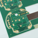
FR-4 remains widely used in industrial applications, but not all FR-4 materials perform equally under harsh conditions. High-Tg, low-CTE laminates are preferred to reduce thermal expansion mismatch and maintain dimensional stability during repeated thermal cycling.
For mixed-signal or RF-enabled industrial systems, dielectric stability directly influences signal integrity and EMI behavior. Stable Dk and low dissipation factor help reduce insertion loss and phase drift, especially in industrial IoT gateways operating at higher data rates.
Solder alloy selection also impacts lifecycle reliability. SAC alloys with optimized silver content are often selected to balance mechanical strength and thermal fatigue resistance. For high-vibration environments, reinforced solder joints and selective underfill strategies may be employed.
Table 1. Typical PCB Material Considerations for Harsh Industrial Environments
| Parameter | Standard FR-4 | High-Tg FR-4 | Industrial-Grade Laminate |
|---|---|---|---|
| Tg (°C) | 130–140 | 170–180 | ≥180 |
| CTE (Z-axis) | High | Medium | Low |
| Thermal Cycling Resistance | Moderate | Good | Excellent |
| Long-Term Dimensional Stability | Limited | Improved | High |
| Suitability for Harsh Environments | Low | Medium | High |
GOPCBA Case Study — Factory Automation Control PCB
Customer Background
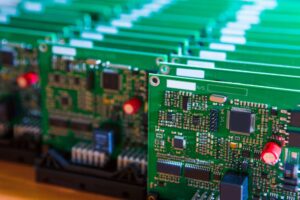
A factory automation equipment manufacturer required industrial PCB assembly for a distributed control module deployed near high-power motors and conveyor systems. The PCB assembly operated continuously in a temperature range of –20 °C to +85 °C and was exposed to constant vibration.
Engineering Challenges
The customer faced recurring field failures related to intermittent I/O signals and power resets after extended operation. Root cause analysis indicated solder joint degradation on through-hole connectors and power devices, aggravated by vibration and thermal cycling.
GOPCBA Assembly Solution
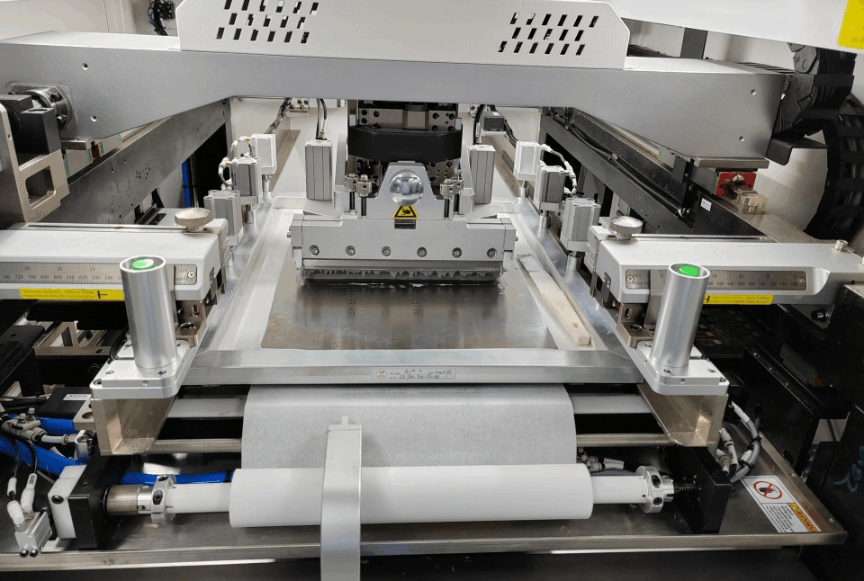
GOPCBA implemented an industrial PCB assembly strategy focusing on process precision and mechanical robustness:
-
Optimized reflow and selective soldering profiles to ensure full barrel fill and void control
-
Reinforced through-hole components using mechanical staking
-
Improved PCB stackup to enhance ground integrity and reduce EMI coupling
-
Implemented AOI, X-ray inspection, and TDR-based impedance verification
Measured Results
Table 2. Assembly Validation Results
| Test Item | Requirement | Measured Result |
|---|---|---|
| Through-Hole Fill Ratio | ≥95% | 98.6% |
| Solder Void Ratio | ≤10% | 4.2% |
| Impedance Deviation | ±10% | ±6.1% |
| Functional Failures after Vibration | 0 allowed | 0 |
| Thermal Cycling Survivability | 500 cycles | 800+ cycles |
Stackup Design & RF Implementation
Even in non-RF industrial systems, stackup design significantly affects assembly reliability and EMI behavior.
GOPCBA adopted a multilayer industrial stackup with dedicated ground planes and power distribution layers to reduce loop inductance and improve power integrity. Controlled impedance routing was applied to communication interfaces and high-speed control signals.
Table 3. Industrial Control PCB Stackup Example
| Layer | Function |
|---|---|
| L1 | Signal / Components |
| L2 | Solid Ground Plane |
| L3 | Power Distribution |
| L4 | Control Signals |
| L5 | Solid Ground Plane |
| L6 | Signal / Components |
This stackup minimized EMI emissions and improved noise immunity while providing mechanical symmetry to reduce warpage during soldering.
Environmental & Reliability Validation
Industrial PCB assembly qualification requires comprehensive environmental validation beyond functional testing.
Thermal cycling tests simulated long-term temperature stress, typically from –40 °C to +125 °C, to evaluate solder joint fatigue and laminate stability. Humidity testing verified insulation resistance and corrosion robustness under high moisture conditions.
Vibration and mechanical shock tests replicated factory floor conditions, ensuring connectors, transformers, and heavy components remained mechanically stable. Solder reflow endurance testing validated assembly resilience to rework and repair scenarios.
Table 4. Reliability Validation Summary
| Test Type | Condition | Result |
|---|---|---|
| Thermal Cycling | –40 °C ↔ +125 °C, 1000 cycles | Pass |
| Damp Heat | 85 °C / 85% RH, 1000 h | Pass |
| Random Vibration | IEC 60068 | Pass |
| Mechanical Shock | 50 g, 11 ms | Pass |
| Solder Reflow Endurance | 3 cycles | No degradation |
Engineering Summary & Contact
Validating assembly precision and lifecycle reliability is essential for industrial PCB assembly deployed in harsh environments. Through controlled assembly processes, robust material selection, optimized stackup design, and comprehensive reliability validation, long-term field performance can be achieved without compromising electrical stability.
GOPCBA focuses on engineer-driven industrial PCB assembly, emphasizing process repeatability, mechanical robustness, and environmental reliability. Our assembly solutions are designed for factory automation, industrial control, power electronics, and industrial IoT systems requiring dependable performance over extended lifecycles.
For engineering consultation, DFM review, or industrial PCB assembly validation support, contact GOPCBA to discuss your application requirements and reliability targets.