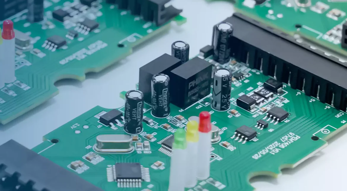
How to Panelize PCBs for SMT Assembly Production
Panelization turns several small boards into one rigid unit that the SMT line can handle. The panel must survive paste printing, placement, reflow, inspection, and depanelization without losing alignment. Each of those steps puts its own demand on spacing, support, and reference marks. A panel that suits the printer may fail at the router. This guide explains the decisions behind a workable panel and the points a buyer should verify before release. Good PCB design and layout sets the foundation, and the panel carries it onto the line.
What Panelization Does for SMT
Individual small boards are hard to feed through automated equipment. A panel gives the machine a larger, stiffer body with known edges and reference points. The line then prints, places, and reflows the whole array in one pass. Handling drops, setup time falls, and the process runs under one set of conditions. After assembly, the units are separated along the connections designed into the panel. The same logic applies to prototypes, where a small batch still needs stable handling.
Panelization also changes how the process is controlled. One panel equals one machine cycle, so a single paste print or placement program covers many units. That reduces variation between boards in the same lot. It also makes inspection simpler, because the camera sees a regular pattern instead of scattered singles. The tradeoff is that one panel defect can affect several units at once. Engineers therefore treat the panel as a process unit, not just a carrier. Buyers should ask how the panel fits the line before approving it.
Choosing a Separation Method
V-cut panelization cuts a V-shaped groove along straight lines between units. It suits rectangular boards with regular outlines and repetitive designs. Separation is fast and leaves a clean edge on simple shapes. The limit is geometry, because curved or irregular outlines cannot follow a straight groove. V-cut also removes some material, so thin boards need care. Check that the remaining web is strong enough to hold the panel through reflow without flexing.
Tab-routed panelization connects each unit to the frame with small bridges of material. A router cuts the outline and leaves the tabs in place. This method handles curved edges, circular boards, and unusual shapes. The tabs must be strong enough to carry the panel through the line and weak enough to break cleanly later. Tab placement matters, because a tab near a tall component can interfere with the router or the fixture. Review tab positions against the component map before release.
Tab-and-hole or stamp-hole structures use a line of small holes along the connection area. The remaining material holds the unit during assembly and separates afterward. This approach is useful when a V-cut cannot follow the outline. The hole pattern needs consistent spacing so stress spreads evenly during separation. Any method leaves a cut edge, so keep components and traces away from the break line. The separation choice should be fixed early, because it drives spacing and frame design.
Setting Panel Size and Spacing
Start with the number of units per panel and check it against machine limits. More units per panel raise throughput but add weight and length. An oversized panel can sag in the oven or jam in the conveyor. Panel thickness, board thickness, and component weight all affect rigidity. Do not simply fill the available area. Confirm the maximum and minimum panel dimensions with the assembly house, then choose a count that stays inside those limits with margin to spare.
Spacing between units must be uniform across the array. The gap has to fit the router bit, the V-cut tool, or the tab structure, plus any fixture clearance. Uneven spacing complicates programming and can cause one unit to sit closer to the frame than another. That difference shows up as inconsistent paste deposits or placement offsets. Keep the gap the same everywhere and record the value on the drawing. Inspection teams then compare the built panel against one agreed number.
Tooling Edges and Fiducials
A production panel usually needs a rail or process edge around the array. The rail gives the conveyor something to grip and the machine something to clamp. It also carries tooling holes and reference marks. Rail width depends on the equipment and the panel weight, so confirm it with the assembly partner. Some lines need rails on two sides, others on all four. The rail should stay clear of components and keep a flat surface for sensors and clamps.
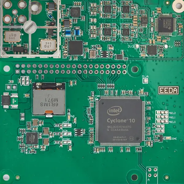
Fiducial marks let the placement machine locate the panel and each unit. Global fiducials sit on the frame and align the whole array. Local fiducials sit near fine-pitch parts and correct for small distortions. The marks need a clear area around them, free of copper, mask openings, and components. Contrast matters, because the camera must see the mark against the surrounding surface. Place fiducials where they stay visible after printing and placement. Missing or blocked fiducials cause placement offsets that are hard to trace later.
Clearance and Orientation Checks
Components near a board edge create risk at several steps. A tall part can hit the conveyor, the fixture, or a neighboring unit. Connectors that overhang the outline can collide with the router or the depanelization tool. Check component height, orientation, and distance to the edge before the panel is released. Pay attention to parts on the bottom side, because they face the conveyor and the support pins. Sensitive parts such as ceramic capacitors should sit away from the break line to limit bending stress.
Keep identical units in the same orientation wherever possible. A single orientation simplifies the placement program, the stencil apertures, and the inspection plan. It also reduces the chance of a mirrored part or a rotated footprint slipping through review. Mixed orientations can be valid for panel utilization, but they need an engineering check. Each rotation changes the paste print direction and the reflow behavior of fine-pitch parts. Document any rotation and confirm it with the assembly team before tooling.
Data Review and Quality Control
The panel data set includes Gerbers, a bill of materials, a centroid file, and fabrication drawings. The centroid file must match the panel, not just the single board, so placement coordinates line up with the array. The bill of materials should list references, quantities, and approved parts. Drawings should show spacing, rails, fiducials, and the separation method. Any special instruction belongs in the same package. Incomplete data forces assumptions, and assumptions at this stage become rework on the floor.
Quality control starts before the first panel is built. The manufacturer checks the revision, the stackup, the component designators, and the process plan against the files. During the run, paste inspection and optical inspection catch print and placement errors early. X-ray helps where joints sit under parts. Electrical test and functional test confirm the assembled unit works. Records from each step show what ran and what was found. A structured quality management system keeps those records usable for the next order.

Who Builds the Panel
Some design teams build the panel in their own CAD tool. That gives full control over arrangement, rails, and fiducial placement. The finished panel still needs review against the manufacturer’s equipment limits. Other teams send the single-board data and let the manufacturer step and repeat it. That works well for standard rectangular boards with simple outlines. The manufacturer knows the line constraints and can size the panel to fit. For complex shapes or tight component clearances, engineering support at this stage saves time.
Whichever route you take, agree on who owns the panel drawing. A clear owner prevents two versions from reaching the floor. The drawing should carry a revision number and a date. When a change is needed, the same owner updates the file and the line confirms it. This is where turnkey PCB assembly helps, because fabrication, assembly, and test sit under one review. Component supply also affects the panel plan, and component procurement should be aligned with the build schedule.
Problems to Catch Early
An oversized panel is a common mistake. It may not fit the conveyor or may flex enough to shift placement. Weak tabs are another risk, because a panel that breaks in transit wastes the whole array. Missing fiducials or marks placed under a component stop the machine from aligning. Uneven spacing complicates routing and paste printing. Each of these problems is cheap to fix on the drawing and costly to fix after tooling. A short review before release catches most of them.
Depanelization deserves its own check. The way units are joined must match the way they will be separated. A router needs clearance around the cut path. A V-cut needs a straight line and enough remaining material. Hand breaking puts stress on joints and can crack ceramic parts. Plan the separation step with the same care as the assembly step. Then confirm that the chosen method does not damage nearby components. This single decision often explains field failures that appear after a good build.
Volume changes the panel plan over time. A prototype panel may hold few units and use generous rails. A production panel may pack more units to cut handling cost. The right answer depends on the line, the board, and the order size. high-volume PCB assembly usually rewards a tighter, well-tested panel, while low volume favors flexibility. Review the panel when the order size changes, and keep the approved drawing with the lot record. That habit keeps repeat orders consistent and makes any deviation easy to spot.
The practical takeaway is simple. Fix the separation method first, then size the panel, then place rails and fiducials, then check clearances. Confirm every number with the assembly house before tooling starts. Keep one approved panel drawing with a revision number, and compare the first article against it. A panel that passes these checks runs through printing, placement, reflow, and separation without surprises. That is the standard to hold on every build.