The Relationship Between PCB Impedance and High-Speed Circuit Boards
With the continuous development of high-speed electronic products, modern circuit boards are required to transmit increasingly faster signals while maintaining stable performance. In advanced electronic applications such as communication equipment, automotive electronics, industrial control systems, and consumer devices, signal quality has become a critical factor affecting product reliability.
One of the most important technologies used to maintain signal quality is PCB Impedance Control. Proper impedance management ensures that electrical signals travel through the circuit board with minimal reflection, distortion, and transmission loss.
For engineers designing high-frequency or high-speed circuits, selecting a professional Controlled Impedance PCB manufacturing partner is essential to achieving consistent performance and production reliability.
What Is PCB Impedance?
Definition of PCB Impedance
Impedance refers to the resistance that a circuit presents to alternating current signals. Unlike simple DC resistance, impedance includes both resistance and reactance caused by capacitance and inductance.
The formula is:
Z = R + jX
Where:
- Z represents impedance
- R represents resistance
- X represents reactance
In PCB applications, impedance determines how efficiently high-frequency signals can travel through copper traces, dielectric materials, and transmission structures.
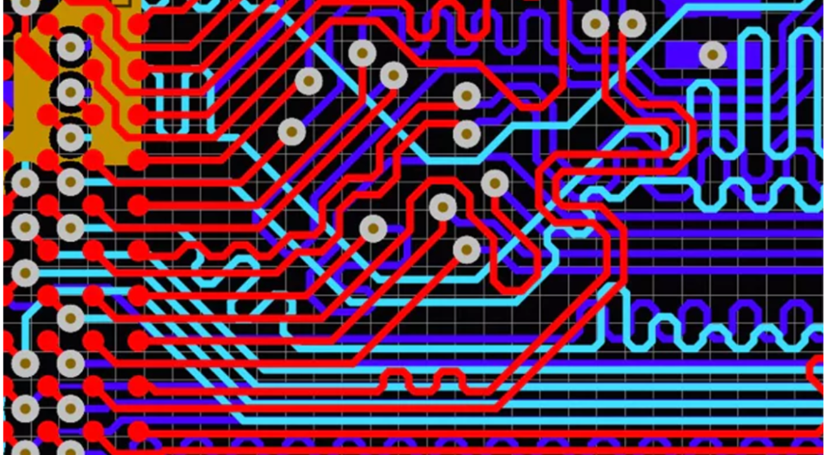
A PCB trace is not only a conductive path but also a transmission line with electrical characteristics. When the impedance value is not properly controlled, signal reflections may occur, causing signal loss, electromagnetic interference, and system instability.
Types of PCB Impedance
Characteristic Impedance
Characteristic impedance is the most common type used in high-speed circuit designs. It describes the impedance experienced by a signal traveling through a single transmission line.
It is mainly influenced by:
- Trace width
- Copper thickness
- Dielectric thickness
- PCB material properties
- Layer stack-up structure
Maintaining consistent characteristic impedance is a key requirement for reliable High-Speed PCB Design.
Differential Impedance
Differential impedance applies to two signal traces transmitting opposite polarity signals.
Common applications include:
- USB interfaces
- HDMI connections
- Ethernet communication
- PCIe systems
- High-speed data transmission circuits
Accurate differential impedance control ensures that paired signals arrive at the receiver with correct timing and minimal interference.
Single-Ended and Common Mode Impedance
Single-ended impedance describes the relationship between an individual signal trace and the reference plane.
Common mode impedance refers to signals traveling in the same direction on multiple conductors.
These impedance types are important for applications requiring strong PCB Signal Integrity, especially in RF and high-frequency electronic systems.
Why Does PCB Need Impedance Control?
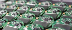
1. Maintaining Signal Integrity
As signal speeds increase, PCB traces behave more like transmission lines rather than simple wires.
Without proper impedance control:
- Signal reflections may occur
- Voltage levels may become unstable
- Data transmission errors may increase
- System performance may decrease
Through optimized stack-up design and precise manufacturing processes, impedance-controlled boards help maintain reliable signal transmission.
For more information about professional circuit board solutions, visit our PCB Manufacturing Services.
2. Supporting High-Speed Electronic Applications
Modern electronic products require faster processing speeds and higher bandwidth. Applications such as servers, networking devices, medical equipment, and automotive systems depend on stable high-frequency signal transmission.
A properly designed Controlled Impedance PCB helps ensure:
- Accurate signal timing
- Reduced electromagnetic interference
- Improved product reliability
- Better overall system performance
3. Reducing Electromagnetic Interference (EMI)
Incorrect impedance values can create unwanted signal reflections and radiation, increasing electromagnetic interference.
Proper impedance design helps:
- Reduce noise
- Improve compatibility with other electronic systems
- Meet industry compliance requirements
Engineers should consider impedance control during the early stages of PCB Design to avoid expensive redesigns during production.
Factors Affecting PCB Impedance
PCB Material Selection
The dielectric constant (Dk) of PCB materials directly affects impedance calculations.
Different materials have different electrical characteristics, including:
- FR-4 materials
- High-frequency laminates
- Low-loss materials
Choosing suitable materials is especially important for RF circuits and high-speed communication products.
Trace Width and Copper Thickness
The geometry of copper traces has a significant influence on impedance.
Important parameters include:
- Trace width
- Copper thickness
- Spacing between differential pairs
- Distance from reference planes
Even small variations during PCB fabrication can cause impedance changes, so manufacturing accuracy is essential.
PCB Layer Stack-Up Design
A reliable multilayer PCB requires careful stack-up planning.
Factors include:
- Signal layer arrangement
- Ground plane positioning
- Power distribution layers
- Dielectric thickness
Professional manufacturers use impedance simulation tools before production to ensure the design meets required specifications.
Learn more about advanced Multilayer PCB Solutions for complex electronic applications.
PCB Manufacturing Factors Affecting Impedance
Copper Etching Accuracy
During PCB fabrication, copper traces are formed through chemical etching processes.
Excessive etching can reduce trace width, while insufficient control can increase width. Both conditions affect impedance performance.
Advanced manufacturing equipment and strict process control help maintain consistent trace dimensions.
Surface Treatment Influence
PCB surface finishes can also affect electrical performance.
Common surface treatments include:
- ENIG
- HASL
- OSP
- Immersion silver
Selecting the correct surface finish helps improve solderability, reliability, and long-term circuit performance.
Testing and Verification
Professional PCB manufacturers verify impedance through testing methods such as:
- Time Domain Reflectometry (TDR)
- Impedance testing reports
- Electrical performance verification
These tests confirm that manufactured boards meet the original design requirements.
For complete assembly and testing capabilities, explore our PCB Assembly Services.
The Importance of Impedance Control in PCB Design
Improving Product Reliability
Stable impedance performance reduces electrical failures and improves the lifetime of electronic products.
Industries that benefit from impedance-controlled PCBs include:
- Automotive electronics
- Telecommunications
- Industrial automation
- Aerospace systems
- Medical devices
Reducing Development Costs

Early impedance planning prevents problems during prototype testing and mass production.
A well-designed PCB reduces:
- Debugging time
- Engineering modifications
- Production delays
Working with an experienced PCB Manufacturing Services provider allows engineers to achieve faster product development cycles.
How Professional PCB Manufacturers Achieve Impedance Control
A reliable PCB manufacturer follows a complete quality management process:
Engineering Review
Engineers analyze:
- PCB stack-up
- Signal requirements
- Material selection
- Impedance targets
Simulation and Optimization
Before production, impedance calculations are performed to optimize:
- Trace dimensions
- Layer structures
- Differential pair routing
Manufacturing Control
During production, manufacturers monitor:
- Copper thickness
- Line width accuracy
- Dielectric thickness
- Process consistency
Final Testing
Finished PCBs undergo inspection and electrical testing to confirm impedance requirements.
More details about production capabilities can be found on our PCB Assembly Manufacturer page.
Conclusion
As electronic devices continue moving toward higher speeds and greater complexity, impedance control has become a fundamental requirement in modern PCB manufacturing.
Proper PCB Impedance Control ensures stable signal transmission, reduces interference, and improves product reliability. From material selection and stack-up design to manufacturing precision and testing, every step influences final impedance performance.
Choosing an experienced PCB partner with advanced engineering capabilities helps businesses develop reliable electronic products faster and more efficiently.
Whether you need prototypes, small-batch production, or large-scale manufacturing, professional PCB Manufacturing Services provide the technical support required for high-performance electronic applications.
Frequently Asked Questions
What is PCB impedance control?
PCB impedance control is the process of designing and manufacturing circuit boards with specific electrical impedance values to ensure accurate high-speed signal transmission.
Why is impedance important in high-speed PCB design?
Impedance affects signal quality. Incorrect impedance can cause signal reflection, distortion, and electromagnetic interference.
How is PCB impedance tested?
PCB impedance is commonly tested using methods such as Time Domain Reflectometry (TDR) to verify that the manufactured board meets design specifications.
What factors affect PCB impedance?
Main factors include PCB material, dielectric thickness, copper thickness, trace width, spacing, and layer stack-up structure.