PCB Manufacturing File Types: Gerber, Drill, BOM & Pick and Place Files
Think about the enormous number of printed circuit boards (PCBs) being manufactured around the world every day. From smartphones and computers to automotive electronics, medical devices, industrial equipment, and aerospace systems, modern electronics depend on reliable PCB production.
Meeting this enormous demand requires PCB manufacturers to use standardized and well-defined manufacturing processes. Standardization improves production efficiency, reduces errors, simplifies communication, and helps manufacturers maintain consistent quality across large production volumes.
Today, PCB Manufacturing and PCB Assembly processes are highly automated. Even the transfer of design data from an engineer’s computer to a manufacturing facility can be largely automated. However, this raises an important question:
What file types are used for PCB manufacturing?
A PCB design cannot simply be sent to a manufacturer as a schematic or native CAD file and expected to produce a finished circuit board. Manufacturers require specific fabrication and assembly data that clearly defines the physical structure, electrical connections, component locations, and manufacturing requirements of the PCB.
This article explains the most common PCB Manufacturing file types, including Gerber files, NC drill files, BOM files, Pick and Place files, Netlist files, and newer PCB data exchange formats. It also explains why accurate file preparation is essential for successful PCB Manufacturing and PCB Assembly.
Why Are File Types Important in PCB Manufacturing?
Choosing the correct PCB file types is an essential part of the transition from PCB Design to physical production.
A complete PCB design workflow must generate manufacturing data that can be correctly interpreted by the PCB manufacturer. Even a perfectly designed circuit can result in an incorrect board if the manufacturing files are incomplete, outdated, incorrectly named, or inconsistent with one another.
Here are several reasons why PCB manufacturing file formats are so important.
1. Prevent Costly Manufacturing and Assembly Errors
Accurate manufacturing files provide the information required to fabricate and assemble the PCB correctly.
For example, fabrication data defines:
- Copper patterns
- Board dimensions
- Solder mask openings
- Silkscreen information
- Drill locations
- Hole sizes
- Layer structures
- Board outlines
- Surface features
If any of this information is missing or incorrect, the manufacturer may produce a board that does not match the original PCB Design.
Manufacturing errors can result in material waste, rework, production delays, and additional engineering costs.
2. Improve Communication Between Designers and Manufacturers
PCB designers and manufacturers may use different software platforms and production systems.
A standardized data format creates a common language between the design team and the manufacturing facility. Instead of relying on proprietary CAD software, the manufacturer receives defined production data that can be imported into its CAM system.
This makes PCB Manufacturing more predictable and reduces misunderstandings between engineering and production teams.
3. Improve Manufacturing and Assembly Efficiency
Modern PCB factories rely heavily on automated manufacturing equipment.
Correct manufacturing files can be imported into CAM systems, CNC drilling equipment, solder paste printers, pick-and-place machines, inspection systems, and other production equipment.
Accurate data reduces manual intervention and helps manufacturers move efficiently from design preparation to production.
4. Support Quality Control and Inspection
Manufacturing data is also important for PCB inspection.
For example, Gerber data can be used as a reference for automated optical inspection (AOI), while assembly data such as BOM and Pick and Place files helps verify component placement.
Accurate files therefore contribute directly to PCB Testing, inspection, and overall product quality.
What Are the Main PCB Manufacturing File Types?
Several different file types may be required depending on whether you are ordering bare PCB fabrication, PCB Assembly, or both.
The most common PCB Manufacturing files include:
- Gerber files
- NC drill files
- Bill of Materials (BOM)
- Pick and Place files
- Netlist files
- Fabrication drawings
- Assembly drawings
- Stackup information
- IPC-2581 or ODB++ data for supported workflows
Each file serves a different purpose.
Gerber Files
Gerber files are among the most widely used data formats in PCB Manufacturing.
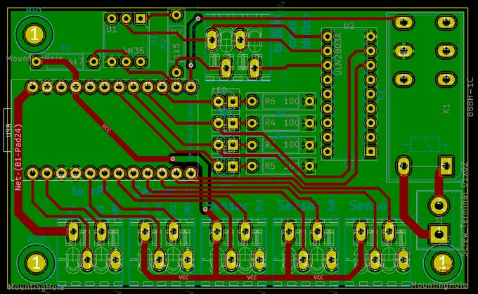
A Gerber file describes the graphical information required to manufacture a particular PCB layer. A complete PCB design usually generates multiple Gerber files, with each file representing a specific layer or manufacturing feature.
Common Gerber layers include:
- Top copper
- Bottom copper
- Inner copper layers
- Top solder mask
- Bottom solder mask
- Top silkscreen
- Bottom silkscreen
- Board outline
- Paste layers
Modern Gerber files are commonly based on the Extended Gerber format, often referred to as RS-274X.
Copper Layer Gerber Files
Copper Gerber files define conductive features such as:
- Copper traces
- Pads
- Polygons
- Planes
- Other copper features
These files provide the manufacturer with the geometric information needed to create the copper pattern.
Solder Mask Gerber Files
Solder mask Gerber files define the areas where solder mask should be applied or where copper pads should remain exposed.
The solder mask helps protect copper and reduces the possibility of accidental solder bridges during PCB Assembly.
Silkscreen Gerber Files
Silkscreen files contain non-conductive markings printed on the PCB surface.
They may include:
- Component reference designators
- Polarity indicators
- Logos
- Labels
- Assembly instructions
- Warning symbols
Accurate silkscreen data makes PCB assembly, inspection, and servicing easier.
Why Are Gerber Files Important?
Gerber files essentially communicate the physical geometry of the PCB to the manufacturer’s CAM system.
However, Gerber files do not necessarily contain every piece of information required for complete PCB fabrication and assembly. Other files and documentation may be required to define drill data, materials, stackup, component information, and assembly requirements.
NC Drill Files
In addition to Gerber files, PCB manufacturers commonly require numerical control (NC) drill files.
These files specify the location and size of holes that need to be drilled into the PCB.
Depending on the design, holes may include:
- Through-holes
- Via holes
- Mounting holes
- Component holes
- Other mechanical holes
The Excellon format is widely used for NC drill data, and .drl is a common file extension, although extensions and naming conventions can vary between CAD tools and manufacturers.
The drill file should always be checked against the PCB design to ensure that hole sizes and locations are correct.
For complex multilayer designs, additional documentation may be required to distinguish different hole types or fabrication requirements.
Bill of Materials (BOM)
The Bill of Materials (BOM) is one of the most important files for PCB Assembly.
Unlike Gerber files, which primarily describe the physical PCB geometry, the BOM provides information about the electronic components required to assemble the board.
A typical BOM may include:
- Reference designator
- Manufacturer part number
- Component description
- Component value
- Package type
- Manufacturer
- Supplier part number
- Quantity
- Approved alternatives
- Assembly notes
For example, reference designators such as R1, R2, C1, U1, and D1 identify individual components on the PCB.
Why Is BOM Accuracy Important?
An incorrect BOM can cause serious assembly problems even when the PCB itself has been manufactured correctly.
Common BOM problems include:
- Obsolete components
- Incorrect part numbers
- Missing components
- Incorrect quantities
- Incorrect package specifications
- Duplicate part numbers
- Unapproved substitutions
The BOM should therefore be reviewed and updated whenever components are changed during PCB Design.
Pick and Place Files
Pick and Place files, also called Centroid files, are used to control automated component placement during PCB Assembly.
These files provide the coordinates and orientation information required by pick-and-place machines.
Typical information includes:
- Reference designator
- X coordinate
- Y coordinate
- Rotation
- Component side
- Package or footprint information
The placement machine uses this information to accurately position components on the PCB before soldering.
Why Do Pick and Place Files Matter?
Even if the PCB fabrication files are correct, outdated Pick and Place data can cause components to be placed incorrectly.
This is especially important after PCB layout changes. If component locations or orientations change, the Pick and Place file should be regenerated together with the other manufacturing data.
The BOM and Pick and Place files should also be consistent with each other.
Netlist Files
A netlist file describes the electrical connections between components in a circuit.
It can contain information such as:
- Component reference designators
- Pin numbers
- Net names
- Electrical connections
- Signal identifiers
The netlist provides a relationship between the logical circuit represented by the schematic and the physical PCB layout.
During PCB Design, the netlist helps ensure that the physical PCB matches the intended electrical design.
In some manufacturing workflows, netlist information can also support electrical testing and verification.
Netlists can be generated by many popular PCB design platforms, including Altium Designer, KiCad, and other ECAD tools.
Fabrication Drawings
A fabrication drawing provides additional manufacturing instructions that may not be fully communicated through Gerber and drill files alone.
A PCB fabrication drawing may specify:
- Board dimensions
- Overall thickness
- Layer count
- Copper thickness
- Material requirements
- Surface finish
- Hole specifications
- Tolerances
- Impedance requirements
- Special manufacturing instructions
For complex PCBs, fabrication drawings can significantly reduce ambiguity between the designer and manufacturer.
Assembly Drawings
Assembly drawings provide additional information for PCB Assembly.
They may show:
- Component reference designators
- Component locations
- Component orientation
- Polarity
- Assembly notes
- Special assembly requirements
An assembly drawing can be particularly useful when the board contains components that require special installation instructions.
Stackup Information
For multilayer PCB designs, stackup information is extremely important.
A stackup defines how the different conductive and dielectric layers are arranged within the board.
It may specify:
- Number of copper layers
- Dielectric materials
- Dielectric thickness
- Copper thickness
- Overall PCB thickness
- Prepreg
- Core materials
- Impedance requirements
For high-speed designs, controlled impedance and signal integrity requirements may depend directly on the final stackup.
Therefore, designers should not assume that the manufacturer can determine the stackup independently without approval.
ODB++ and IPC-2581
Although Gerber remains one of the most widely used PCB manufacturing formats, modern PCB workflows also support more comprehensive data exchange formats.
ODB++
ODB++ is a PCB design and manufacturing data exchange format that can package multiple types of PCB manufacturing information into a structured database.
Depending on the workflow, it can reduce the need to manage numerous separate files.
IPC-2581
IPC-2581 is another standardized PCB data exchange format designed to communicate design and manufacturing information between CAD/CAM systems.
It can contain information related to:
- Layer structure
- Materials
- Copper features
- Components
- Drill data
- Manufacturing information
- Assembly information
The availability and preferred format depend on the PCB manufacturer’s systems and workflow.
For this reason, designers should always confirm accepted data formats with their chosen manufacturer before generating final production files.
What Challenges Can Occur When Transferring PCB Files?
Data exchange between PCB Design software and manufacturing systems can create several potential problems.
Identifying these problems before production can prevent expensive manufacturing and assembly errors.
Incomplete Gerber Layers
When sending Gerber files to a manufacturer, make sure every required layer is included.
For example, if a top silkscreen file is missing, the manufacturer may reasonably interpret the design as having no top silkscreen.
A missing solder mask, copper, or board-outline layer can have even more serious consequences.
Incorrect Component Coordinates
Pick and Place files may contain incorrect component coordinates after a design revision.
If the PCB layout changes, the corresponding assembly files should also be regenerated.
The Gerber files, BOM, Pick and Place files, and assembly documentation should all represent the same revision of the design.
Confusing File Names
Poor file naming can make manufacturing data difficult to interpret.
Instead of using unclear names, use a consistent naming system that identifies the board, layer, and file type.
For example:
ProjectX_TopCopper.gbrProjectX_BottomCopper.gbrProjectX_TopMask.gbrProjectX_TopSilkscreen.gbrProjectX_Drill.drlProjectX_BOM.xlsx
The exact naming convention should be agreed upon with the manufacturer because different CAM systems may use different conventions.
Outdated Documentation
Another common problem is sending outdated documentation with a revised PCB.
For example, the PCB layout may have been updated while the BOM or Pick and Place file still contains information from an earlier revision.
This can result in:
- Incorrect components
- Incorrect component placement
- Assembly delays
- Production rework
- Product failures
Version control is therefore an important part of a reliable PCB Manufacturing workflow.
Missing Manufacturing Requirements
Some requirements may not be obvious from Gerber files alone.
For example, manufacturers may need additional information about:
- PCB material
- Surface finish
- Copper thickness
- Board thickness
- Impedance
- Special tolerances
- UL or other compliance requirements
- Assembly requirements
These requirements should be clearly documented before production begins.
How to Prepare PCB Manufacturing Files Correctly
A structured pre-production review can significantly reduce errors.
Before submitting files to a manufacturer, follow these steps:
Step 1: Complete the PCB Design
Finish the schematic and PCB layout before generating final manufacturing files.
Step 2: Run Design Rule Checks
Run DRC to identify potential layout problems such as:
- Clearance violations
- Unconnected nets
- Trace-width violations
- Incorrect footprints
- Manufacturing rule violations
Step 3: Verify the Board Stackup
Confirm layer count, materials, copper thickness, dielectric structure, and overall board thickness.
Step 4: Generate Manufacturing Data
Export the required Gerber files, NC drill files, fabrication drawings, and other manufacturing documentation.
Step 5: Generate Assembly Data
If assembly is required, generate the BOM, Pick and Place files, and assembly drawings.
Step 6: Check All Files Together
Do not review each file independently.
Make sure the:
Gerber files + Drill files + BOM + Pick and Place files + Drawings
all correspond to the same PCB revision.
Step 7: Review the Final Manufacturing Package
Before uploading the files to your PCB Manufacturing partner, verify that:
- All required files are present.
- Layer names are clear.
- Board dimensions are correct.
- Drill information is correct.
- Component quantities are correct.
- Component coordinates are correct.
- Polarity information is correct.
- BOM part numbers are current.
- Manufacturing requirements are documented.
- All files belong to the same revision.
This final review can prevent many avoidable production problems.
PCB Manufacturing File Types Comparison
| File Type | Primary Purpose | Common Use |
|---|---|---|
| Gerber | PCB layer graphics | PCB fabrication |
| NC Drill / Excellon | Hole locations and sizes | PCB drilling |
| BOM | Component information | PCB Assembly |
| Pick and Place | Component coordinates and orientation | Automated assembly |
| Netlist | Electrical connections | Design verification/testing |
| Fabrication Drawing | Manufacturing specifications | PCB fabrication |
| Assembly Drawing | Component placement/reference | PCB Assembly |
| Stackup | Layer and material structure | Multilayer PCB |
| ODB++ | Integrated manufacturing data | PCB fabrication/assembly |
| IPC-2581 | Structured PCB data exchange | Design-to-manufacturing workflow |
Best Practices for PCB Manufacturing Data
To make the transition from PCB Design to production more reliable, follow these best practices:
- Use the manufacturer’s preferred file formats.
- Confirm the required file package before production.
- Use consistent file naming.
- Maintain strict revision control.
- Regenerate manufacturing files after major design changes.
- Check Gerber files using a Gerber viewer.
- Verify drill files independently.
- Check BOM part numbers and component availability.
- Compare Pick and Place data against the final PCB layout.
- Include fabrication and assembly drawings when appropriate.
- Clearly document special requirements.
- Keep all manufacturing files synchronized.
- Obtain manufacturer approval for unusual materials or fabrication requirements.
How Kingda Can Help With PCB Manufacturing
Choosing an experienced PCB manufacturing partner is important because manufacturing quality depends not only on the design itself but also on how accurately the design data is interpreted and converted into a physical product.
Kingda can support projects requiring PCB Design, PCB Manufacturing, and PCB Assembly, depending on the specific project requirements.
When selecting a PCB manufacturing partner, consider:
- Supported PCB technologies
- Layer capabilities
- Material options
- Copper thickness
- Surface finishes
- Manufacturing tolerances
- Assembly capabilities
- Component sourcing
- Electrical testing
- Quality control
- Production volume
- Engineering support
Providing a complete and consistent manufacturing data package can help Kingda and other manufacturing partners understand the intended design more accurately and reduce unnecessary production delays.
Frequently Asked Questions About PCB Manufacturing Files
What file types are needed for PCB manufacturing?
The most common files include Gerber files and NC drill files for bare PCB fabrication. For PCB Assembly, manufacturers typically also need a BOM and Pick and Place files. Fabrication drawings, assembly drawings, stackup information, and other documentation may be required for more complex projects.
What is a Gerber file used for?
A Gerber file describes the graphical information for a specific PCB layer or manufacturing feature. Manufacturers use Gerber data in their CAM systems to prepare copper, solder mask, silkscreen, and other PCB fabrication processes.
Is a BOM required for PCB manufacturing?
A BOM is generally required when the manufacturer is also providing PCB Assembly. It identifies the components required to populate the PCB. For bare-board fabrication only, a BOM may not be necessary.
What is a Pick and Place file?
A Pick and Place file, also called a Centroid file, provides automated assembly equipment with component coordinates, rotation, side information, and other placement data. It is primarily used during PCB Assembly.
What is an NC drill file?
An NC drill file contains information about the locations and sizes of holes that need to be drilled into the PCB. Excellon is a commonly used format for PCB drill data.
Are Gerber files enough to manufacture a PCB?
Not always. Gerber files provide important layer geometry, but manufacturers may also require NC drill files, fabrication drawings, stackup information, material specifications, and other production requirements depending on the PCB design.
What is the difference between Gerber and ODB++?
Gerber commonly represents individual PCB layers as separate manufacturing files, while ODB++ can package a broader range of PCB design and manufacturing information into a structured data set. The appropriate format depends on the manufacturer’s workflow.
What happens if PCB manufacturing files are incorrect?
Incorrect or incomplete files can result in manufacturing defects, incorrect drilling, missing layers, incorrect component placement, assembly errors, production delays, and additional rework costs. Reviewing the complete manufacturing package before production is therefore essential.
Conclusion
PCB manufacturing depends on accurate communication between the design engineer, PCB manufacturer, and assembly team. While modern PCB Design software makes circuit development faster and more sophisticated, the design must eventually be converted into manufacturing data that production equipment and CAM systems can interpret correctly.
Gerber files, NC drill files, BOM files, Pick and Place files, Netlist files, fabrication drawings, assembly drawings, and stackup information each serve different purposes within the PCB production workflow.
For simple boards, a basic Gerber and drill package may be sufficient. For complex multilayer or assembled PCBs, a more comprehensive manufacturing package may be required. Formats such as ODB++ and IPC-2581 can also provide structured alternatives for certain design-to-manufacturing workflows.
Ultimately, successful PCB Manufacturing starts with accurate, complete, and synchronized design data. By carefully reviewing every manufacturing file before production, engineers can reduce manufacturing errors, improve PCB Assembly efficiency, shorten production delays, and achieve more reliable final products.