Solar Panel PCB Guide: Design, Manufacturing and Cost
Solar energy is growing faster than almost any other power source, and every solar installation depends on a small but critical component: the circuit board that connects the cells and manages the power. A solar panel PCB is not an ordinary board. It carries higher currents, survives years of outdoor exposure, and must keep working through heat, moisture, and ultraviolet light. Engineers and buyers who understand how these boards are designed and made can extend system life, cut maintenance, and reduce project cost. This guide explains what a solar panel PCB is, how it works, the materials and design rules that matter, the manufacturing process, realistic costs, and how to select a dependable supplier.
What Is a Solar Panel PCB?
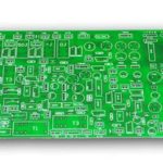
A solar panel PCB is a printed circuit board designed for photovoltaic systems. Its job is to connect the solar cells, collect the direct current they generate, and route that power toward the load, the battery, or the inverter. Unlike a consumer electronics board, it must handle significant current, tolerate high ambient temperatures, and resist moisture, salt, and ultraviolet radiation for decades. The board often carries bypass diodes, current sensing resistors, and connectors, and in modern systems it may host the monitoring and control electronics that optimize power harvesting.
The difference between a solar PCB and a standard board comes down to three things: copper thickness for current capacity, substrate choice for thermal performance, and protective finishes for outdoor reliability. A board designed without those three considerations will degrade quickly under the sun, no matter how well the rest of the system is engineered.
How a Solar Panel Circuit Board Works
Photovoltaic cells produce direct current when sunlight excites electrons in the semiconductor material. The circuit board collects that current through the cell tabbing and bus structure and carries it along copper traces to the output terminals. Diodes on the board protect the panel: when one cell is shaded, bypass diodes provide an alternative path so the shaded cell does not overheat or drag down the whole string. Resistors and sense lines feed voltage and current information to the monitoring electronics, and in battery-based systems the board routes power through charge regulation stages before it reaches the storage bank.
Because the voltages and currents are much larger than typical signal levels, every millimeter of trace matters. A narrow trace or a thin copper layer becomes a bottleneck that wastes energy as heat, so designers calculate trace width against expected current, then add margin for temperature. Good layout also keeps the low-voltage sensing traces away from the high-current power paths so measurements stay accurate.
Key Components and Materials
Four material groups define solar board performance. The base substrate is the first. FR-4 is affordable and adequate for many junction box and monitoring boards, while aluminum-base boards conduct heat away from power components far more effectively and are common when the PCB also serves as a heat spreader. Polyimide flex materials appear in portable and foldable solar products where thinness and flexibility matter. The copper layer is the second group: heavy copper of 2 oz, 3 oz, or more carries high current with low loss, which is why power-grade solar boards specify thicker copper than ordinary electronics. Solder mask and protective coatings form the third group. They shield traces from humidity and oxidation, and UV-stable coatings slow the yellowing and embrittlement caused by sunlight. The fourth group is the components themselves: bypass diodes, Schottky rectifiers, current sensors, connectors, and, on smart panels, the microcontroller and wireless module that report output and health data.

Types of Solar PCBs
Solar applications use several board constructions. Rigid boards are the workhorse of residential and commercial fixed installations: they are durable, easy to assemble, and inexpensive at volume. Flexible boards are thin and bendable, which suits portable chargers, wearable solar devices, curved surfaces, and off-grid products that fold or roll. Hybrid and multilayer boards combine rigid and flex sections and are found in advanced solar storage systems, smart grid equipment, and battery management electronics where multiple functions share one compact assembly. Multilayer boards also help when monitoring, communications, and power conversion circuitry must coexist in a small junction box. Choosing the right type is a trade-off between cost, environment, and mechanical constraints, and it directly affects both efficiency and lifetime.
Solar Panel PCB Design Rules
A board that must survive two decades outdoors is designed differently from one that lives inside a plastic case. Thermal management comes first. Solar cells and the surrounding electronics get hot, and aluminum substrates or arrays of thermal vias carry heat to a heatsink or the mounting frame. Without this path, power components age quickly and output falls as temperature rises. Weather resistance is second. The design should keep moisture from pooling near solder joints, use conformal coating where humidity is a risk, and specify finishes that resist corrosion. Electrical efficiency is third: heavy copper, generous trace widths, and short power paths reduce resistive loss, which is pure waste in an energy system. Finally, keep serviceability in mind. Connectors and fusing should be accessible, because a panel that cannot be repaired cheaply will be scrapped prematurely. Most of these decisions are made during the PCB design and layout phase, where a change costs nothing more than design time, while the same correction after fabrication costs tooling, material, and weeks of delay.
Solar PCB Manufacturing Process
Production follows a familiar sequence with solar-specific emphasis. The process starts with prototype design and testing to confirm the circuit handles the expected current and temperature. After approval, the copper layers are etched and laminated into the stackup, holes are drilled and plated to connect layers, and heavy copper work is finished with the required surface treatment. Component assembly places diodes, regulators, connectors, and control chips, and then quality checks verify conductivity, insulation, thermal behavior, and solder joint integrity. Reputable factories run electrical testing on every power board because a single open joint in a high-current path can burn out in the field. Full PCBA testing, including thermal and functional tests, separates boards that last from boards that fail quietly after a season in the sun.
Applications of Solar Panel PCBs
Solar boards appear across the whole renewable energy ecosystem. Residential and commercial photovoltaic systems use rigid boards in junction boxes and monitoring units, where long-term durability is the priority. Large utility-scale plants specify multilayer high-power boards for combiner boxes, string monitors, and tracker controllers that manage megawatts of power. Solar-powered IoT devices, including street lights, agricultural sensors, and surveillance cameras, pack generation, battery management, and wireless communication onto compact boards. Off-grid products such as portable generators, camping power stations, and remote telecom power supplies often use flexible or hybrid boards because space and weight are limited. Whatever the setting, the board is the connective tissue that turns raw panel output into usable power, and manufacturers with dedicated energy PCBA experience understand the power, isolation, and reliability rules that ordinary consumer assembly lines often miss.
Solar Panel PCB Cost
Pricing for solar boards is usually quoted by area because board size, not component count, drives material use. Rigid boards typically range from about 10 to 30 dollars per square meter of board area for standard FR-4 constructions, making them the economical choice for residential systems. Flexible boards run roughly 20 to 50 dollars per square meter, reflecting the cost of polyimide material, and are used where portability justifies the premium. Custom multilayer boards with heavy copper, controlled thickness, or integrated thermal management commonly start above 50 to 80 dollars per square meter, with complexity pushing the number higher for industrial and storage systems. Component assembly, coating, and testing add to the total, so the most reliable way to estimate a project is to send a complete stackup and current specification to a manufacturer and compare detailed quotes rather than per-board price lists.
Choosing a Solar PCB Manufacturer
The right supplier keeps a solar project alive for decades, so the selection criteria are stricter than for ordinary boards. Confirm the factory can build the construction you need, whether rigid, flexible, or hybrid, and ask how many layers and what copper weights it supports. Check certifications such as ISO quality systems, UL recognition where required, and RoHS compliance, because these are the minimum evidence of process discipline. Evaluate price transparency and lead time together: a quote that is complete and a delivery date that is realistic matter more than the lowest number. Look for engineering support as well, because solar layouts benefit from a DFM review that catches thermal or current-capacity problems before tooling. A full-service partner will handle the PCB manufacturing, assembly, and testing as one workflow, which shortens the supply chain and removes a common source of miscommunication.

Junction Boxes, Monitoring and Quality
Two product areas illustrate how solar boards are used in practice. Junction boxes are attached to the back of every panel and contain the bypass diodes plus the output connections; their boards must survive the hottest point of the panel while carrying the full string current, so they are built with heavy copper and heat-tolerant materials. Monitoring and optimization units are increasingly mounted at the panel or combiner level, where a microcontroller reads current and voltage, watches for faults, and communicates over wireless or power-line links. These mixed power and signal boards need careful separation between the high-voltage path and the sensitive measurement circuitry, and they benefit from conformal coating to resist condensation. Quality control in both cases starts with the board supplier: incoming material checks, impedance and insulation testing where relevant, and functional testing of the finished assembly. A factory that documents each of these steps can trace a field failure back to its cause, which is the difference between a one-time fix and a systematic improvement.
Future Trends in Solar PCBs
The solar board market is moving quickly. Ultra-light flexible boards are appearing in building-integrated photovoltaics and portable devices. Higher voltage systems are pushing designers toward wider, thicker copper and more robust insulation. Smart panels now ship with integrated monitoring, which places microcontrollers, sensors, and wireless radios on the board itself and raises the importance of reliable PCB assembly for mixed power and signal designs. Recyclable substrates and halogen-free laminates are gaining ground as sustainability requirements tighten, and advanced thermal materials continue to improve the power density of junction boxes and microinverters. Companies that keep pace with these trends gain both efficiency and a longer service life.
Production Lead Time and Ordering Tips
Planning a solar board order is straightforward when the specification is complete. Define the operating voltage and maximum current, the ambient temperature range, whether the board will be coated, and the mechanical mounting. Send these with the Gerber files and stackup so the factory can confirm copper weight, layer count, and material in one pass. Prototype quantities typically ship in one to two weeks, while production orders need two to four weeks depending on copper weight and volume. Ordering in advance of the busy season avoids surprises, and a single partner that manages fabrication, component sourcing, assembly, and testing keeps the whole flow under one quality system.
Frequently Asked Questions
Q1. What is the difference between a solar panel PCB and a normal PCB? A solar PCB handles much higher current, tolerates outdoor heat and moisture, and often uses heavier copper and protective coatings that ordinary circuit boards do not need.
Q2. Which material is best for solar PCBs? FR-4 is economical for junction boxes and monitors, aluminum-base boards suit power applications that need heat spreading, and polyimide flex is best for portable or curved solar products.
Q3. How much does a solar panel PCB cost? Rigid boards commonly cost 10 to 30 dollars per square meter, flexible boards 20 to 50 dollars, and custom multilayer power boards can exceed 50 to 80 dollars per square meter.
Q4. How long do solar PCBs last? With correct materials, conformal coating, and current margin, a well-built board can last as long as the panel itself, typically 20 to 25 years in outdoor service.
Q5. Do solar panels need custom PCBs? Most junction boxes and monitoring circuits benefit from a custom layout because current capacity, enclosure shape, and connection points differ between panel models.
Conclusion
Solar panel PCBs connect the promise of photovoltaic energy to reliable, everyday power. Understanding how they work, which materials handle heat and weather, and how cost scales with complexity helps engineers and buyers choose boards that perform for decades rather than seasons. Pairing a sound design with a manufacturer that runs disciplined fabrication, assembly, and testing is the surest route to a solar product that is efficient, durable, and economical over its full life.