




PCBA DFM Analysis: Improve Yield and Reduce Risk Guide
PCBA DFM analysis is a review of the PCB design and assembly requirements before production begins. DFM stands for design for manufacturability, and its purpose is to find design features that will be difficult or expensive to build. Many common PCBA defects can be traced to design decisions made before a board ever reaches the factory. By reviewing layout, component spacing, solder pads, stackup, materials, and test access early, the design team can improve yield and reduce cost.
This guide explains what a professional PCBA DFM report checks, why it is important, and how to use it to lower production risk.
DFM should be performed as early as possible, but it is still useful after layout is complete. A review before the Gerber files are finalized can catch errors that would otherwise be discovered only after the first sample fails.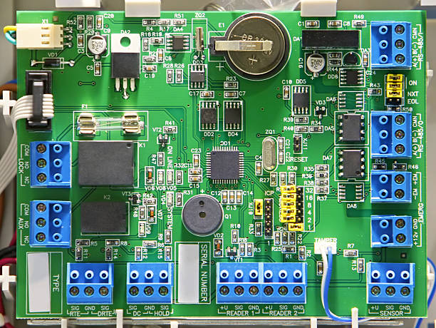
Why PCBA Yield Is Important
Yield is the percentage of assembled boards that pass inspection and testing on the first attempt. A low first-pass yield means more rework, more scrap, higher material cost, and longer delivery time.
Some defects are caused by the manufacturing process, but many are caused by design features that are not compatible with standard assembly. A small pad, a tight component, or a missing test point can force the factory to use a more difficult process.
Design review is the best opportunity to correct these issues because changes are still inexpensive before tooling and material are committed.
The BOM should also be reviewed for assembly issues. If a component is obsolete, hard to source, or incompatible with the required soldering process, the DFM report should flag it before production starts.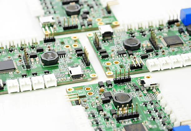
What Does DFM Analysis Check?
A DFM analysis reviews the PCB layout for manufacturability. It checks trace width and spacing, pad size, solder mask clearance, via types, and annular ring. The review also checks component placement and orientation.
For assembly, DFM verifies that components can be placed by the available machines and soldered without excessive difficulty. It checks for obstacles that prevent the nozzle from reaching a component and for components placed too close together.
The report may also review board size, panel layout, tooling holes, and edge clearance so the PCB can be handled efficiently through production.
Via placement also affects manufacturability. Vias under BGAs may require filling or capping, while vias placed too close to pads can steal solder or weaken the pad. The DFM report should identify via structures that need special processing.
Layout and Routing Risks
Very fine traces are harder to etch and inspect than wider traces. If a trace width is near the factory’s minimum, the yield may be lower and the cost higher. The design should use the widest practical trace for the available space.
Clearance is another risk. Traces that are too close can create shorts, especially when solder mask registration is not perfect. The DFM report should identify clearance values that are outside the recommended range.
Ground and power planes should also be reviewed for thermal relief, isolation, and the ability to carry current without excessive heating.
Stencil design is part of DFM as well. The aperture shape, area ratio, and thickness should provide the correct solder volume for each pad. A bad stencil design can create bridges or insufficient joints even when the PCB layout is acceptable.
Solderability and Pad Design
Solder joints are influenced by pad size, shape, spacing, and the amount of copper around them. A pad connected to a large ground plane may steal heat during soldering, producing a cold joint if no thermal relief is used.
BGA pads, QFN pads, and fine-pitch footprints need special care. The solder mask opening, stencil aperture, and pad finish must be matched to the component and soldering process.
DFM review should confirm that all pads are accessible and that the board can be cleaned and inspected after assembly.
The review should also consider orientation for solder paste inspection and AOI. If two identical components are placed in different directions, the inspector may need additional programs or the board may be more likely to be assembled incorrectly.
Component Placement Risks
Components should be oriented consistently to make assembly and inspection easier. Polarity marks, pin 1 indicators, and reference designators should be visible after placement.
Tall components should not block the placement nozzle from reaching low components, and sensitive parts should be kept away from heat sources. Very large components may need special handling or additional support.
Component spacing should allow solder mask dams, inspection access, and rework tools to reach the board without damaging neighbors.
For controlled impedance designs, DFM must verify the dielectric thickness and copper weight against the target impedance. Small changes in material thickness can cause a 50 ohm trace to become a 45 ohm trace.
Material Selection and Finish
The laminate and finish must match the application. High-speed boards need stable dielectric material, high-temperature boards need higher Tg, and outdoor products may need a coating or robust finish.
The surface finish affects solderability, shelf life, and cost. ENIG is good for fine-pitch parts, while OSP is economical for many standard products. The DFM review should confirm that the finish supports the selected assembly process.
Material thickness, copper weight, and impedance targets should also be confirmed with the manufacturer before production.
Panelization should be considered together with testability. If test points fall on the panel rail, they may be inaccessible after depaneling. The design should place production test features where they can be used at the correct stage.
Testability Review
A design can be well manufactured but difficult to test. ICT needs test points large enough for probes and arranged with consistent spacing. FCT needs access to connectors, programming headers, and calibration points.
If the board contains a microcontroller, the design should include a way to program it during production. If a sensor requires calibration, the test plan should explain how the calibration value will be stored.
Testability review reduces the time spent building custom fixtures and troubleshooting inaccessible circuits.
DFM also reduces hidden costs such as engineering communication, expedited freight for replacement parts, and customer line downtime. The value of preventing these issues is often much larger than the cost of the DFM service itself.
How DFM Reduces Cost
Fixing a design problem before production is much cheaper than reworking boards after assembly. DFM prevents scrap, reduces engineering queries, and shortens the time between order release and delivery.
It also lowers component waste. When pad sizes and footprints are correct, the assembly process produces fewer missing, shifted, or damaged components.
For high-volume products, even a small yield improvement creates a large saving over thousands of boards and reduces the need for extra spare stock.
The DFM process should also establish a deadline for the customer response. Design files that are not approved for a long time can become obsolete while the customer is deciding, especially if component suppliers change their product status.
The DFM Report Process
DFM usually begins with the customer sending Gerber files, drill data, BOM, stackup, and assembly drawings. The factory compares the design with its process capability and customer requirements.
The report should list each risk, its likely impact, and a recommended change. Some items are critical, while others are suggestions that depend on the customer’s cost or performance target.
The customer reviews the report and approves the final design before production. This creates a shared understanding of the board’s manufacturability.
DFM feedback should be practical and specific. Saying that a trace is too thin is not enough; the report should recommend a width and explain what yield or inspection risk is avoided.
Common DFM Findings
Common findings include insufficient annular ring, solder mask slivers, components too close to the board edge, missing tooling holes, inadequate thermal relief, and unsupported heavy components.
Other findings may relate to test access, BOM consistency, or the use of components that are difficult to source. These issues should be resolved before the PCB order is placed.
A complete DFM report reduces the number of surprise questions that appear during production.
Working with a DFM-Capable Partner
Ask the supplier whether it provides DFM feedback for every order or only when requested. A supplier that proactively reviews the design can prevent problems the customer may not have considered.
The review should be performed by engineers who understand both PCB fabrication and PCBA assembly, because design choices affect both processes.
When DFM is integrated with PCB design and layout, PCB manufacturing, and SMT PCB assembly, the customer benefits from a single quality view from design to delivery. DFM results should also be linked with PCBA testing so the design supports both production and verification.
Conclusion
PCBA DFM analysis is a powerful tool for improving yield and reducing risk before production. Layout, solderability, materials, component placement, and testability all affect the final quality of the board.
By reviewing the design early and acting on the recommendations, manufacturers and customers can reduce rework, shorten lead time, and produce reliable PCBA products at a lower total cost.


