




SMT Visual Management and Factory Process Guide
SMT visual management helps factory operators see the normal state of the production line at a glance. A well-organized SMT workshop uses labels, color codes, instruction boards, and clear process displays so that every person can understand the job requirement without searching for information. Visual management also makes abnormalities visible before they become defects.
Surface mount production depends on people, machines, materials, and methods working together. The operator must know the solder paste condition, temperature range, component storage rule, and machine safety requirement for each process step.
This guide explains important SMT workshop controls and the role of visual management in a PCBA factory.
Operating Environment Requirements
The SMT factory should maintain a controlled workshop temperature. A common comprehensive management standard is 25 plus or minus 3 degrees Celsius.
Stable temperature keeps solder paste viscosity consistent and prevents components and boards from absorbing moisture. Humidity control is also important for component storage and soldering quality.
The production area should be kept clean and free from dust, fibers, and unnecessary materials. ESD flooring and grounded work surfaces protect sensitive components.
Visual temperature and humidity displays allow operators and managers to confirm that the environment is within range during every shift.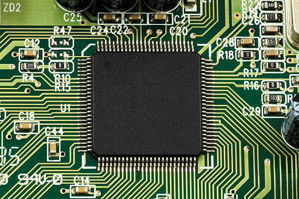
Machine Safety and Operator Skill
SMT mounter operation requires experienced technical personnel and general managers who have received professional training. The machine cannot produce good boards by itself if the operator does not understand its setup and safety requirements.
Machine operation should follow a written safety procedure. The operator must know the emergency stop, conveyor control, feeder handling, and cleaning rules.
A well-run SMT line provides high reliability, high throughput, low defect rate, and good high-frequency performance in the final product. These results depend on controlled placement and reflow conditions.
Visual job aids at the machine can remind the operator of the correct setup and error response.
Advantages of Surface Mount Products
SMT components are small and light. The size and weight of a surface mount assembly can be only half, or even one tenth, of the size and weight of a traditional through-hole component.
When SMT chips are selected for a product, the overall electronic product volume can be reduced by 40 to 60 percent and its weight can be reduced by 60 to 80 percent under the same function.
The small product size makes it possible to design compact devices, reduce enclosure cost, and improve portability. SMT also improves automation and production efficiency.
High assembly density and short connections reduce electromagnetic and radio frequency signal interference, improving the performance of high-frequency circuits.
Solder Paste Printing Preparation
Before solder paste printing, the operator should prepare all necessary tools. The material list includes the paste tool, steel squeegee, wiping paper, airflow into the stencil cleaner, and mixing knife.
Wiping paper is used to clean the stencil bottom between boards. The cleaner removes paste residue from apertures so that every print has the same volume.
The mixing knife prepares the solder paste before it is loaded into the printer. Paste should be mixed according to the supplier instruction to restore the correct consistency.
A visual checklist at the printer helps the operator confirm that every required tool is present before production.
Solder Paste Alloy and Flux
Many SMT factories use solder paste made from a tin-lead alloy with an alloy ratio of 63 percent tin and 37 percent lead. This eutectic alloy has a clear melting point and good wetting behavior.
Solder paste is divided into two main parts: tin powder and flux. The flux removes oxides, reduces the surface tension of the molten tin, and prevents the metal from oxidizing again during reflow.
The volume ratio of tin powder to flux is approximately 1 to 1, while the weight ratio is approximately 9 to 1. The correct ratio gives the paste enough metal to form a strong joint and enough flux to clean the surface.
Paste composition should be matched to the board finish, component finish, and reflow profile.
Thawing and Using Solder Paste
Refrigerated solder paste must be thawed and brought back to room temperature before use. The paste should not be reheated with an external heat source because heat can destroy the flux and change the paste rheology.
The paste should be removed from the refrigerator, allowed to warm gradually, and then mixed gently. Opening the container too early or heating it too quickly creates inconsistent printing.
After the paste has been placed on the printer, it should be used within the recommended working time. Old paste should be removed from the stencil and discarded according to the material control rule.
A visual label on the paste container shows the open date and expiry time.
BGA and IC Storage
The most easily overlooked step in PCBA manufacturing is the storage of BGA and IC chips. These components are moisture-sensitive and can be damaged if they absorb moisture from the air.
BGA and IC chips should be stored in their original sealed packaging in a dry environment. Desiccants and humidity indicator cards should be used inside the storage container.
When a package is opened, the operator should check the floor life and bake the components if the time limit has been exceeded. Baking removes moisture before the components are exposed to reflow heat.
Component storage should be controlled to keep the core parts dry and prevent oxidation of the terminations.
What Is Visual Management
Visual management is a factory management method that uses signs, colors, displays, and standard labels to communicate information. Employees can see the production, operation, and management requirements directly instead of receiving a long verbal instruction.
A visual board can show the current product, target output, machine status, quality data, and maintenance schedule. The operator can understand the plan and the actual state from one glance.
Visual management makes the organization more transparent and reduces the need for unnecessary supervision. It helps every employee know his or her position and role in the organization.
Improving Efficiency Through Visual Information
Information flow is a prerequisite for efficient work. When employees can obtain operation management information directly, they can clearly understand the job requirements and take correct action.
Some factories create many inspectors whose main job is to supervise the implementation of instructions. This is often a sign of poor information flow. A highly managed enterprise sends information smoothly both vertically and horizontally.
Visual management is an effective way to achieve smooth information and accurately convey instructions to employees. It eliminates unnecessary intermediate management links.
When managers enter the production site, good visual management gives them more opportunity to obtain real work information. Management decisions can then be based on the actual state of the workshop.
Avoiding Inappropriate Instructions
Management instructions should be determined according to the specific needs of the production site. If managers do not understand the actual situation, they may issue instructions that interfere with production.
Visual data shows the current condition of machines, quality, and materials. This helps managers issue instructions that accurately reflect the workshop and avoid disrupting normal work.
Managers should use the visual displays when reviewing the line, so decisions are connected to real process data instead of assumptions.
Error Prevention Through Visual Management
In production, various problems and exceptions occur every day. If these problems are not found and handled in time, normal production is affected.
Visual management reflects the ideal state and the actual state, or the normal state and the abnormal state. When a display changes color or a board shows an error, employees can see that something is different from ordinary.
This makes it easier for workers to find problems and anomalies in their own jobs. They can identify the issue early and formulate a countermeasure before it creates defective boards.
Visual signals also help managers see problems at a glance when they enter the production area.
Using Visual Management in SMT Production
SMT lines can use visual boards for line balancing, changeover countdown, machine alarm status, and material shortage alerts. Operators should know what each signal means and how to respond.
Color-coded feeders, reels, and component bins reduce the chance of loading the wrong part. Labeled nozzles and cleaning tools are returned to the correct position after use.
Inspection stations should display the accepted component images and defect examples. This helps inspectors compare the actual board with the correct reference.
A high-quality SMT PCB assembly process is easier to control when the workshop is organized and visible.
Visual management supports quality management by making process data available to everyone who needs it.
When a new product is introduced to SMT PCB assembly, visual setup sheets reduce mistakes during changeover.
The visual system should also be connected to PCBA testing results so that defects can be traced quickly to the responsible process step.
Before the line runs, the PCB design and layout should include clear markings that make visual inspection easier.
Conclusion
SMT factory control requires a stable environment, controlled materials, and trained operators. Solder paste, component storage, and machine setup must follow clear rules.
Visual management improves communication and efficiency by showing the normal and abnormal states of the workshop. It helps employees and managers find problems early and take the correct action.
When process control and visual management work together, the SMT factory can maintain high yield, low defect rate, and reliable PCBA output.


