SMT Ceramic Capacitors: A Practical Guide to MLCC Assembly
Ceramic capacitors are among the most common parts on a surface mount board, yet they cause a surprising share of assembly problems. A part that is electrically simple can still crack, tombstone or lose capacitance when the dielectric, package and solder process are not matched to the application. This guide looks at multilayer ceramic capacitors from the factory floor, where selection, placement and inspection decide whether the circuit behaves as designed.
Start With the Dielectric, Not the Price
MLCCs are grouped by dielectric behavior. C0G and NP0 parts hold capacitance across temperature and voltage, which makes them suitable for filters, oscillators and timing circuits. X7R and X5R parts offer much higher capacitance in a small package, but their value changes with temperature, applied voltage and age. Y5V parts change even more and should be reserved for decoupling where a wide tolerance is acceptable.
The first design check is therefore the actual electrical requirement. A bill of materials that substitutes a high-capacitance X5R part for a C0G part may save space and cost, but it can move a filter frequency or change an oscillator load. Buyers should ask for the dielectric class, tolerance and voltage rating, not only the capacitance value.
Package Size and Placement Accuracy
Small packages save board area, but they also reduce the pad area available for a reliable joint. An 0402 or 0201 part needs tighter placement accuracy, cleaner stencil apertures and better board support than an 0805 or 1206 part. The placement program must use the correct nozzle, feeder and component library, and the operator should confirm that the reel matches the job packet before the line starts.
Pad geometry matters as much as machine accuracy. Pads that are too wide can let the part shift during reflow, while pads that are too narrow can produce insufficient fillets. The stencil aperture should be sized for the pad and the paste type, and the first article should be checked under magnification before the batch continues.
Solder Joints and Tombstoning
Tombstoning is common when one end of a small capacitor heats faster than the other or when the paste volumes at the two pads are uneven. A balanced aperture, a symmetric pad layout and a controlled reflow profile reduce the risk. The oven profile should follow the paste supplier’s recommendation and should be verified with a profiler rather than copied from another product.
Thermal shock is another concern. Large ceramic parts can crack when the board moves quickly from a hot zone to a cold zone or when a hot soldering iron touches the termination. Preheating, controlled cooling and careful rework practice protect the ceramic body. Cracks may not show up at functional test, so visual inspection and, where needed, cross-sectioning are part of a serious quality plan.
Inspection and Test
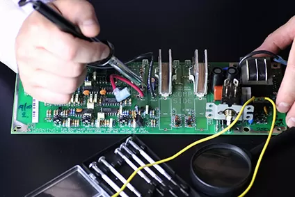
Automated optical inspection can catch missing parts, wrong polarity on nearby components and obvious solder defects, but it cannot see every hairline crack. Electrical test confirms capacitance and opens, while sampling plans and lot records show whether the process is stable. For high-reliability products, the customer should agree on the inspection level and the evidence that will be supplied with each batch.
A practical PCBA testing plan combines visual checks, electrical measurements and process data. If a batch shows a cluster of cracked parts, the factory should review stencil support, board depanelization and reflow cooling instead of simply replacing the capacitors.
Procurement and Traceability
Counterfeit or mislabeled MLCCs are a real risk in the open market. A reputable component procurement service buys from authorized channels, checks the date code and packaging, and keeps the reel label with the lot record. When a design change or a field return appears months later, that record is the fastest way to trace the part back to its source.
The factory should also control moisture-sensitive parts and storage conditions. Ceramic capacitors are less sensitive than some packages, but the surrounding components and the paste are not. A dry, organized store protects the whole kit.
Working With gopcb
gopcb reviews the BOM, the pad layout and the assembly notes before production, then runs the SMT assembly process with documented setup and inspection. Our engineers can suggest an alternative dielectric or package when a part is hard to source, and we will explain the trade-off rather than substitute silently.
If you are planning a new board or correcting a mature design, send your files and requirements. You will receive a manufacturability review, a clear quotation and a production plan that covers the ceramic capacitors as part of the whole assembly, not as an afterthought.