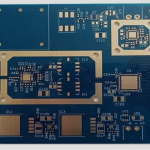
PCB Panelisation: Tabs, Rails and Utilisation
Why Boards Are Panelised
A bare board is processed individually only in the smallest shops. Everywhere else the design is stepped into a panel so that a standard size sheet can carry many boards through imaging, plating, lamination, assembly and test on the same equipment with the same handling. Panelisation is therefore a manufacturing decision that has to be made before the fabrication data is released, and it is one of the few places where the designer directly controls assembly cost, because the panel determines how many boards a machine can place components on per cycle and how much material is scrapped.
Rails and the Frame
The rail is the border of the panel, and it exists to give the handling and placement equipment something to grip. The width is set by what the assembly line needs: conveyor rails, clamping in the printer, and the edge clearance on the placement machine all impose a minimum, typically in the region of 5 to 10 mm, with a wider rail where the machine clamps from above. Tooling holes are placed in the rails, not in the board, so that the panel can be located by pins on every machine in the line. Fiducials for the stencil printer and the placement machines also live in the rails, and they need a clear area around them so that the vision system can find them.
Tabs and Breakaway Design
The tabs are the small bridges of material that hold each board in the panel, and they are where most depanelling problems originate. A tab should be wide enough to carry the board through the line without flexing but narrow enough to break cleanly. Perforated or V-notched tabs break predictably, and a tab with a routed slot on each side breaks along a line the designer chose rather than one the process chose. Tab position matters as much as tab size: place them where a break will not damage a nearby plated hole or a fine trace, keep them out of the region where a connector will be pressed, and provide enough tabs that the board is supported during placement of heavy components. Where a board is small, the tabs often have to hold it through the whole assembly process, so the count and the placement carry mechanical load rather than convenience.
Utilisation and Panel Size
The obvious goal is to fit as many boards as possible into the sheet, but the constraint is not only the outline. Panel size is limited by the largest panel the equipment can process, and by the sag of a large thin panel through the ovens. Very dense layouts with narrow margins between boards reduce the space available for routing and make the milling step slower, and they can leave so little material that the panel is too flexible to handle. The practical balance is to aim for strong utilisation while keeping enough clearance between boards for the profiling tool and enough rail for the line. Where the board outline is irregular, nesting the shapes can recover area that a simple grid wastes.

Fiducials, Tooling and Clamping
Fiducials should be placed on the panel, in global positions, and on each board or each group where local accuracy is needed. Their size, their contrast and the clear area around them are defined by the placement machine’s vision system, and a fiducial that is partly covered by a neighbouring board is worse than no fiducial. Where the board carries a fine pitch component, adding local fiducials near the component improves placement accuracy at that location. Tooling holes in the rail should be specified as plain holes rather than plated, and their positions should match the pins on the line, since a mismatch produces a placement offset on every board in the panel.
Assembly Considerations
Panelisation decides how the board behaves in the printer, the placement machine and the reflow oven. A board supported only by narrow tabs can bow during placement and shift the paste deposits, and it can sag in the oven for the same reason. Boards of mixed thickness in one panel are impractical because the printer and the placement machine work at one height. Where the board carries castellated edges or edge plating, the tabs have to be positioned so that depanelling does not tear the plated feature. Where the board will be tested in panel form, the test points need access and the panel has to fit the fixture.
Small Boards and Odd Shapes
Very small boards are usually stepped with several boards joined by internal tabs so that the group is handled as one unit, then separated at the end. Odd shapes are nested, and the spare area can be used for test coupons rather than discarded. Where a product is a long, narrow strip, the panel is often rotated so that the long axis runs across the panel rather than along it, which improves the utilisation and reduces the amount of material lost at the edges. In all of these cases the rule is the same: the panel is designed for the process, and the board outline is only the starting point.
Documenting the Panel on the Drawing
The panel drawing is a fabrication deliverable, not an internal note, so it has to state what the shop is expected to build. The useful content is the panel outline, the array layout with step and repeat counts, the rail width, the position and diameter of the tooling holes, the fiducial positions, the tab geometry with its break line, and the direction of any V-score or break line relative to the board. Also state whether the panel may be re-arranged to improve utilisation, and whether the shop may substitute its own standard rail dimensions. Many fabricators will panelise the design themselves if they are given the board outline and the assembly constraints, and letting them do so is often faster than imposing an array that does not suit their equipment. Whichever route is taken, the finished panel should be reviewed against the assembly line before the order is placed, because a panel that cannot be clamped is discovered at the printer rather than at the drawing desk.
FAQ
What is panelisation? Arranging multiple boards on a single panel with rails and tabs so that a standard manufacturing size can carry them through fabrication and assembly.
How wide should the rail be? Enough for the conveyor and clamps of the assembly line, commonly 5 to 10 mm, with more where the machine clamps from above.
Where should tabs go? Where the break will not damage a plated hole or a fine trace, with enough tabs to support the board during placement and depanelling.
Do fiducials go on the board or the rail? Global fiducials go on the panel, and local fiducials are added near fine-pitch components where extra accuracy is needed.
Does a denser panel always cost less? No. Cramming boards together can slow profiling, weaken the panel and leave no room for tooling, which costs more than the material saved.
Conclusion
Panelisation is a manufacturing decision that happens to be drawn by the designer, so the rails, tabs, fiducials and clearances should be set with the assembly line in mind rather than with the outline alone. Balance utilisation against handling, put the breakaway features where a break is harmless, and give the vision systems what they need. Panel and breakaway capabilities are described under PCB capabilities, the profiling step belongs to PCB manufacturing, and the assembly consequences are covered by PCB assembly. Depanelling and the assembly sequence continue into SMT PCB assembly in 2026.