AOI Programming and Escape Prevention
What AOI Does
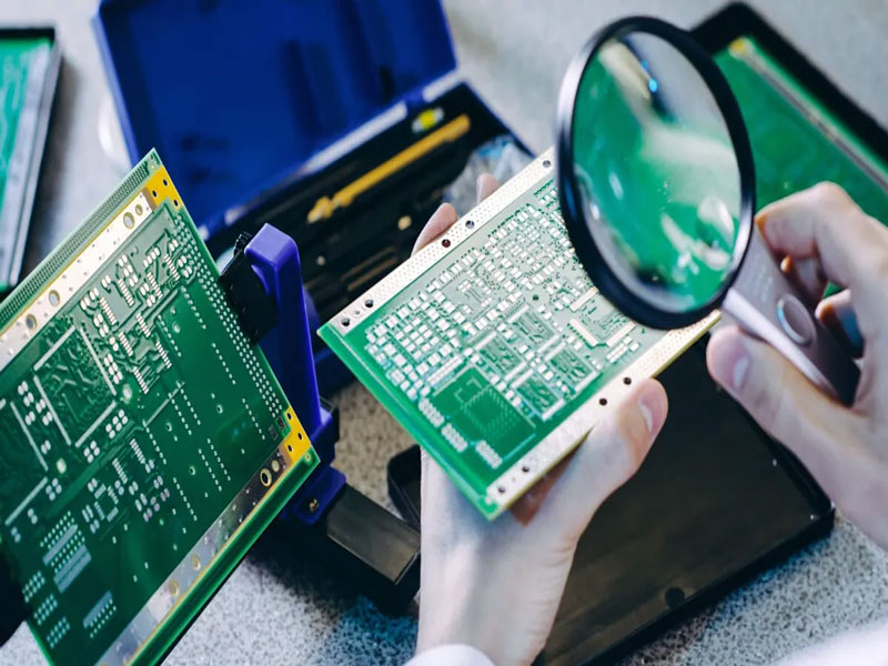
An automated optical inspection system photographs the board after reflow and compares what it sees with a reference, using a mixture of image processing and measurements to decide whether each component and joint is acceptable. It finds missing parts, reversed parts, shifted parts, wrong parts, tombstoning, bridging and insufficient solder, and it does so far faster than a person. What it does not do is judge, and the whole of the programming effort is about encoding the judgements that a human inspector would make, in a form that produces few false calls and few escapes.
How the Algorithm Decides
Most systems combine two methods. The first is a comparison against a reference image, usually captured from a known-good board, which is fast and effective for presence and position. The second is a set of measurements, such as the area of solder on a joint, the offset of a part, the angle of a lead and the colour of a fillet, which is more robust than a pixel comparison where the process varies. The parameters that decide acceptance are thresholds, and the threshold is where the trade-off between false calls and escapes lives. Setting a threshold tighter finds more defects and rejects more good boards.
Teaching and Library Quality
The quality of the inspection depends on the quality of the library. Each package type needs a model that describes where the solder should be, where the part body should sit and which features distinguish a good joint from a bad one. A library entry copied from a different product with a different pad geometry will produce false calls on good boards and may never flag the defect it was meant to catch. Where a design uses a new package, the library entry should be built from a real board and validated against deliberately defective samples rather than accepted from a catalogue.
False Calls and Escapes
A false call is a good joint reported as bad, and an escape is a bad joint reported as good. The two are in tension: loosening the thresholds reduces false calls and increases escapes. Both have a cost, but they are not equal. A false call costs a re-inspection, and too many of them cause the operators to override the system, at which point the inspection has no value at all. An escape reaches the customer. The practical approach is to set the thresholds so that the false call rate is low enough that operators trust the system, then to verify separately that the escape rate is acceptable by testing the system with deliberately defective boards.

Programming for a New Product
The sequence that works is to start from the placement data, generate the inspection programme automatically, then review it part by part rather than accepting the default. The review should check the reference image, the search window, the thresholds for the packages that are hardest to inspect, and the treatment of parts that are hidden or that cannot be seen clearly. Areas that the camera cannot see, such as a joint under a package body, should be explicitly excluded with a note rather than left to produce unreliable results. Where a board has been run before, the programme should be carried forward with each change documented, because a programme that is edited without a record becomes impossible to diagnose.
Coverage and Blind Spots
Every optical system has blind spots: joints under a package, reflections from a tall component, the underside of a lead, and the area shadowed by a connector. These are not programming problems and cannot be fixed by a threshold. They should be identified on the inspection plan and covered by another method, which for a hidden joint means X-ray or electrical test. Listing the blind spots explicitly is what turns an inspection from an assumption into a covered requirement.
Verifying the System
The only way to know that an inspection is working is to test it with defects. A verification set is built from boards with deliberately introduced faults of the kinds the system is supposed to find, and the system is run against them periodically to confirm that it catches each one. The set should include the subtle defects, not only the obvious ones, because a system that catches a missing part and misses a tombstoned one looks effective until the escape reaches the field. Many lines build the verification set from the defects that actually reached the customer, which is a useful way to make sure the same escape cannot recur.
Handling the Output
The output of an inspection step is a disposition, and the disposition has to be defined for each defect class: repair, re-inspect, or scrap. Where the operator is allowed to override, the override reason should be recorded, since a system that is overridden frequently is either mis-programmed or being asked to make judgements it was not designed for. The repair rate is worth tracking after a programme change, because it is the quickest indication that a threshold has moved in the wrong direction or that the process has shifted.
AOI in a Mixed Inspection Strategy
An optical inspection is one instrument among several, and its value is greatest when it is assigned the defects it is good at and relieved of the ones it is not. It is excellent at presence, orientation and position, good at visible solder volume, and poor at anything hidden under a package or behind a tall component. A strategy that assigns AOI to the visible attributes, X-ray to the hidden joints and electrical test to the functional behaviour gives each method a defined job and makes the gaps between them explicit. Where the three overlap, the overlap should be deliberate, aimed at the defects that are most likely to escape, rather than accidental. Reviewing the strategy whenever a new package type is introduced is what keeps the coverage whole, because a new package almost always creates a new blind spot somewhere in the coverage.
FAQ
What does AOI check? Component presence, orientation, position and solder appearance using image comparison and measurement against programmed thresholds.
What is a false call? A good joint reported as defective. It costs re-inspection time and erodes operator trust in the system.
What is an escape? A defective joint reported as good, which is the more expensive error because it reaches the customer.
How do I know the AOI works? By running a verification set of boards with deliberately introduced defects and confirming that each one is caught.
Can AOI see under a package? No. Hidden joints are a blind spot and need X-ray or electrical test coverage instead.
Conclusion
AOI programming is the act of encoding a judgement, and its value depends on the library, the thresholds and the verification rather than on the machine. Build library entries from real boards, balance false calls against escapes deliberately, list the blind spots and cover them another way, and test the system with known defects. Inspection sits alongside PCBA testing, the assembly process it monitors is described in SMT PCB assembly, and the discipline that keeps it reliable belongs to quality management. Programmes are normally established during prototype PCB assembly in 2026.