Automated Optical Inspection in SMT
What AOI Does
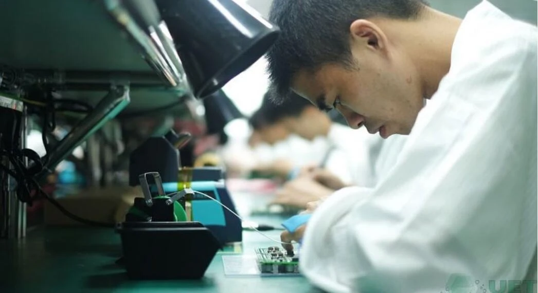
Automated optical inspection uses a camera and software to compare what is on the board with what the program expects. It checks that each component is present, that it is in the right position and orientation, that the solder joints have the expected appearance, and that no foreign material or damage is present. It is fast, it is consistent, and it does not get tired, which is why it has replaced a large part of the manual visual inspection that was once done at a bench. What it does not do is judge the inside of a joint or inspect under a package.
Where It Sits in the Line
AOI can be placed after paste printing, after reflow, or both. After printing it verifies the deposits, which is the earliest point at which an error can be caught and corrected before any component is placed. After reflow it verifies the assembled joints and the placement. Using both gives the best information about where a defect originated: a defect found after reflow that was not present after printing is a process problem in placement or reflow, while one present in both is a printing problem. The choice depends on the product and the cost of a defect, and the benefit of two stations is usually larger on a complex or high value assembly.
Writing the Program
The program is generated from the placement data, which means it is only as good as the data. Each component’s package type, its expected position and its orientation tolerance are used to place an inspection window, and the software learns what a good joint looks like from sample images. That learning step is where most of the effort lies: the program must be trained on boards that are known good, and the sample must include the normal variation in the process, otherwise the inspection will reject sound joints and miss the bad ones. A program copied from a similar product without retraining is a common source of both escapes and false calls.
Setting the Limits
Every inspection parameter has a threshold, and the thresholds decide the balance between escapes and false calls. A limit that is too tight rejects good joints, which consumes operator time and erodes confidence in the system; one that is too loose lets defects through. The limits should be set from the known good sample and then adjusted by reviewing the calls: every false call is a chance to correct a threshold, and every escape is a chance to tighten one. The review should be recorded, so that the reasoning behind a setting is available when someone asks why it is what it is.
Lighting and Its Influence
The inspection depends on the image, and the image depends on the lighting. Different colours and angles of light reveal different features: a low angle emphasises the profile of a joint, a high angle emphasises the surface, and colour can separate the solder from the silkscreen or the mask. The lighting must be stable over time and matched to the program, so a change of lamp or a drift in intensity invalidates the settings. Where a program was developed on one machine and moved to another, the lighting must be equivalent, otherwise the results will not be comparable even though the software is identical.
What AOI Cannot See
AOI looks at surfaces, so it cannot inspect the joints under an area array package, the metallurgy of a joint, or the internal structure of a plated barrel. It is also limited in judging the quality of a joint whose surface looks acceptable but which has not bonded, such as a head in pillow defect. Those are the territory of X-ray and of electrical test. AOI is also influenced by the view angle, so a joint behind a tall component may be partially hidden. Knowing the boundary is what allows the inspection strategy to combine AOI with the other methods rather than relying on it for everything.
Making AOI Worth Its Cost
AOI earns its place when the program is accurate, the calls are reviewed, and the data is used. A machine that runs with a high false call rate and whose calls are cleared without review is an expensive way to move boards from one conveyor to another. The data should be analysed by defect type and by position, so that a pattern becomes visible and a process correction follows. Where the same defect appears repeatedly, the response is a change to the printer, the placement or the reflow, not a tighter limit on the inspection. The inspection reports the problem; the process decides whether it recurs.
Operator Review and the Feedback Loop
An AOI system is only as useful as the review that follows it. The operator who examines a called defect should record whether it was a real defect or a false call, because that judgement is what allows the thresholds to be corrected. Where the review is treated as a formality and the calls are cleared in bulk, the program never improves and the machine becomes a bottleneck that everyone learns to ignore. Where the review is taken seriously, the false call rate falls over the first weeks and the inspection begins to produce information about the process rather than noise about the machine.

FAQ
What does AOI check? The presence, position and orientation of components and the appearance of solder joints, at speed and consistently.
Where should AOI be placed? After printing, after reflow or both; using both makes it possible to locate where a defect originated.
Why do AOI programs produce false calls? The limits are too tight or the sample was not representative, so sound joints are rejected.
Does lighting matter? Yes. The program is tied to the lighting, so a change of lamp or intensity invalidates the settings.
What can AOI not inspect? Joints under a package, joint metallurgy and internal structures, which need X-ray or electrical test.
Conclusion
AOI is fast, consistent and bounded, so train it well, set the limits deliberately and use the data it produces. It reports defects rather than preventing them. Inspection strategy belongs to quality management, the line it monitors is described in SMT PCB assembly, and the electrical confirmation is part of PCBA testing. Inspection planning for a new assembly begins during prototype PCB assembly in 2026.