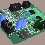
DVR PCB: Structure, Function and Key Components
A digital video recorder is a device that must accept several camera streams at once, compress them, store them continuously and serve them back to a viewer who may be anywhere on the network. The DVR PCB is where all of that happens, and its design is a good illustration of how a board is shaped by throughput and by the requirement to run unattended for years. The electrical function is not exotic, but the combination of continuous operation, storage and network connectivity sets requirements that a consumer board would not have.
What a DVR Board Does
The board receives video from analogue or digital cameras and converts each stream into a format the processor can handle. It compresses those streams using a standard codec, writes the result to a hard drive or a memory card, and simultaneously serves live and recorded video to a client over the network. On top of that it manages the power rails, the real time clock, the front panel and the alarm inputs.
Doing several of those things at once is what makes the design interesting. Compression is computationally heavy and the storage interface is bandwidth limited, so the board is really a small data handling system that happens to have a video front end attached to it. Any bottleneck in one of those paths shows up as dropped frames or as a recording gap, which in a security application is the failure that matters most.
Structure and Layer Count
Most commercial DVR boards are built as a multilayer board, typically four to eight layers, and the layer count is driven by the high speed interfaces rather than by the component count. The interface between the processor and the memory runs at hundreds of megahertz, the storage interface is comparable, and the Ethernet connection requires controlled impedance and a magnetics block. None of those will work well without a solid reference plane.
The usual arrangement puts the high speed routing on the outer layers, a continuous ground plane immediately beneath it, and the power distribution on an inner layer with a second ground to complete the stack. The board is often around a hundred by a hundred and fifty millimetres, which is small enough that the thermal load has to be spread deliberately rather than left to the enclosure. Our layer assignment notes describe how that arrangement is planned.

Video Compression and Signal Path
Compression is performed in hardware rather than in software, because doing it in software would require a processor far more powerful than the product could afford. The encoder block in the system on chip takes the incoming frames, produces the compressed stream and writes it to memory, from which it is moved to storage. The path between the encoder, the memory and the storage interface is the busiest part of the board and should be laid out as directly as possible.
The video input side is a mixed-signal problem. Analogue camera inputs need termination, filtering and often a buffer amplifier before they reach the decoder, and the ground reference for those inputs must be clean even though the board also carries switching supplies and a hard drive. Keeping the input section on its own area of copper, with its own return path to the supply, is what prevents the drive current from appearing as noise on the video.
Storage, Interfaces and Connectors
The storage interface deserves particular attention because it carries high speed differential signals along a cable that may be several centimetres long. Impedance must be controlled, the pair must be length matched, and the connector must have a solid ground reference. Where the drive is powered from the same board, the current it draws during spin-up is a significant transient that the supply has to absorb without disturbing the rest of the system.
Network connectivity adds another set of constraints. The Ethernet magnetics and the connector need their own ground reference arrangement, and the differential pair between the processor and the magnetics must be kept short and matched. Our design release checklist covers the checks that should be made on these interfaces before the layout is released.
Thermal Design for Continuous Operation
A DVR runs twenty-four hours a day, often in a cupboard or a rack where the ambient is warm and the airflow is poor. That is the opposite of the intermittent duty cycle that most consumer electronics are designed for. Dissipation from the processor, the memory and the storage device accumulates, and the board has to spread it into the enclosure rather than concentrate it under the largest package.
Thermal vias beneath the exposed pad of the processor, connected to internal planes that spread the heat laterally, are the standard measure. Copper area on the underside of the board, a metal chassis as a heat sink, and a fan in the larger models complete the path. Where a fan is used, its intake must avoid the dust that settles on the board, because a dust layer on a hot component is both a thermal and a reliability problem. Our thermal management article describes how the copper areas are sized.

Reliability, EMC and Long Term Operation
Interfaces to the outside world are where a board like this gets damaged. Camera cables run long distances and pick up surges, the network cable can carry a potential difference between buildings, and the power input is exposed to whatever the installation provides. Protection at each of those points, using transient suppressors, series impedance and a defined return path, is what keeps the board working after the installation has been struck once.
Emission control is the other requirement. The processor clock, the memory interface and the switching supply all radiate, and the product has to meet the applicable EMC standard. A continuous ground plane, short return paths, controlled impedance interfaces and filtering at the connectors are the measures that make compliance achievable without a redesign. This is also why high frequency laminates are occasionally used in the digital section of a demanding product, although standard FR-4 with a well planned stack-up is sufficient for the frequencies involved here.
Testing and Field Considerations
Functional test covers the video inputs, the compression path, the storage write and read, the network interface and the alarm inputs. The tests that matter most in practice are the long duration ones: a soak test at full channel count with continuous recording and simultaneous remote viewing, run long enough for the thermal steady state to be reached and for any intermittent fault to appear.
In the field, the most common causes of a recording gap are a drive that has reached its write endurance limit, a thermal shutdown caused by dust or a failed fan, and a network configuration error rather than a hardware failure. Designing the board so that the temperature of the critical components can be read back through software makes those cases much easier to diagnose, and it costs nothing beyond a thermistor and a spare input on the monitoring device.
FAQ
How many layers does a DVR PCB need? Four layers is the practical minimum for a small channel count, and six to eight layers is common once several channels, a Gigabit Ethernet interface and a hard drive interface share the board.
Why does a DVR need a hard drive interface with controlled impedance? The interface runs at high speed over a cable, so the signals behave as transmission lines. Without a controlled impedance and a matched length, the data eye closes and the drive reports errors that look like a failing disk.
What causes a DVR to lose the last few minutes of recording? Usually the data is still in the write buffer when power is removed, or the file system was not closed cleanly. A supply that holds up long enough for the write to complete, and a clean shutdown path, prevent it.