DVD Player PCB: Structure, Function and Repair Guide
A DVD player is one of the last mass-market products built around a mechanical system that must be controlled to microscopic precision, and the board that does the controlling is a useful case study in mixed-signal design. A DVD player PCB reads an optical pickup, decodes a compressed digital stream, converts it to analogue or digital outputs, drives two servo motors and manages a front panel and a remote receiver, all on a board that had to be cheap enough for a consumer product.
What the Main Board Does
The optical pickup returns a weak analogue signal from the disc surface, and the first job of the board is to amplify it, extract the servo error signals and recover the digital data. Those error signals, focus error and tracking error, are used in closed loops that keep the laser on a track that is a fraction of a micrometre wide while the disc spins at a rate that changes continuously as the head moves outward.
Once the data is recovered, it passes to the decoding chain. Error correction removes the damage caused by scratches and dust, a buffer holds the corrected data so that playback continues through a brief interruption, and the decoder reconstructs the video and audio streams defined by the disc format. The output stage then produces the analogue video, the digital audio and, on later players, an HDMI stream. A microcontroller coordinates the whole sequence and interprets the front panel and the remote control.
Key Components and Their Roles
The main control chip handles the user interface, the menu logic and the sequencing of the system, and it is the part that executes the firmware. Alongside it sits the dedicated decoder, which performs the computationally heavy work of reconstructing the compressed video and audio. Separating the two functions keeps the control firmware simple and lets the decoder be optimised for throughput rather than for general purpose work.
The analogue front end, the driver stages for the spindle and sled motors, and the output buffers are the parts that connect the digital core to the physical world. The servo drivers are essentially power amplifiers delivering current to the motors in response to the loop commands, and their layout matters because they switch significant current close to circuits that are handling signals measured in millivolts.
Board Structure and Layer Count
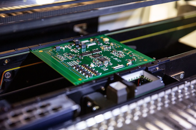
Most players use a two-layer board, with the main components on the top face and a ground pour on the bottom. Four layers appear in the more capable models, where a dedicated ground plane and a power plane reduce the interference between the servo driver section and the analogue signal path. The additional layers are justified by noise performance rather than by routing density, which is a useful reminder that layer count is often a signal integrity decision rather than a density one. Our layer assignment notes describe how that split is planned.
Component placement follows the signal chain. The analogue front end sits as close as possible to the connector from the optical pickup, because the signal at that point is weakest and most vulnerable. The decoder and the memory sit next to each other, and the output connectors are kept away from the servo drivers. Where a high dissipation part is used, thermal vias beneath it carry heat into the ground pour on the opposite side, which acts as a heat spreader for the whole board.
Materials and Construction
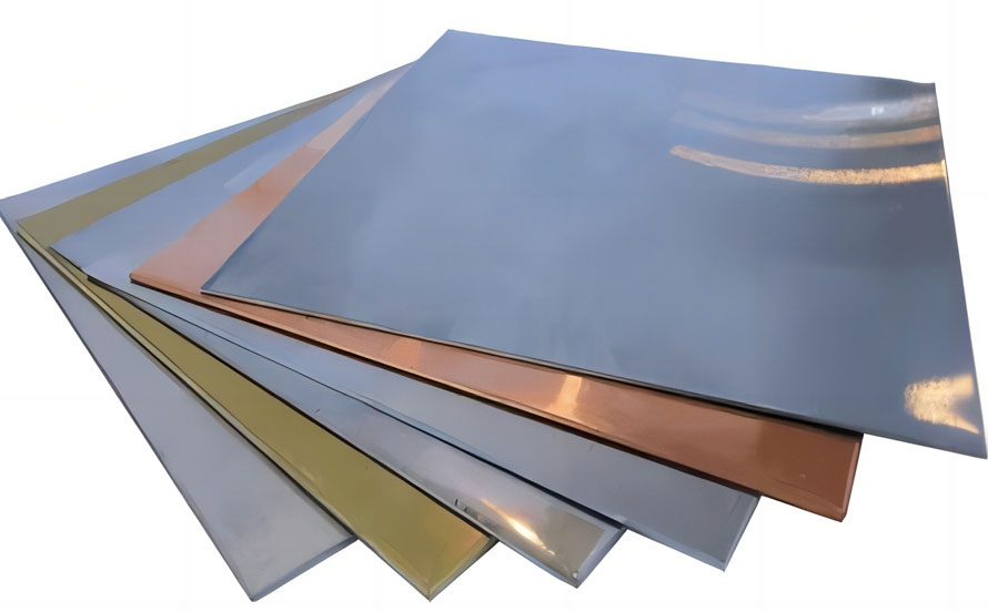
Standard FR-4 is universal in this class of product, in a thickness chosen to suit the mechanical support the board provides as well as its electrical function. Copper weight is usually one ounce, with heavier copper reserved for the servo driver area where the motor current flows. Surface finish is chosen for solderability and cost rather than for fine pitch performance, since the finest packages on a player board are still comfortably within the capability of a standard finish.
Because the board carries an optical system, contamination control matters more than on an ordinary consumer board. Flux residue and dust can migrate inside the enclosure and settle on the optical pickup, where even a small particle degrades read performance. Cleaning and a conformal coat on the sensitive areas are common, and the coating is also the reason the board survives the humid environment of a living room.
Noise, Grounding and the Analogue Path
The board combines motor drive, a switching supply and a video output stage that may operate at tens of megahertz, so a ground plane is essential rather than optional. The servo driver return currents are the largest in the system and are kept on their own path back to the supply, while the analogue section is referenced to quiet copper that the motor currents do not share. Joining the two only at a defined point avoids the situation where a fraction of the motor current flows through the analogue reference.
Shielding is used selectively. The decoding section may be covered by a metal can to keep its clock harmonics out of the video output, and the analogue output filters are placed close to their connectors. Our thermal management material describes how the heat spreading copper is arranged around the parts that dissipate most.

Failure Modes and Repair Practice
Most player faults are not board faults. The optical pickup wears out, the mechanism loses lubrication and the belt that drives the tray perishes, and all three produce symptoms that look electrical. Before suspecting the board, the standard sequence is to check the supply rails under load, confirm that the spindle runs at the correct speed, and observe whether the focus and tracking loops can be driven at all.
When the board is at fault, the failure is usually a capacitor that has degraded, a solder joint that has cracked around a connector or a power device, or a regulator that has failed and taken a section of the board with it. Electrolytic capacitors are the most common single cause, because they age with temperature and the player runs warm. A joint that has cracked shows up as an intermittent fault that changes when the board is flexed, and reflowing the suspect joint is often enough. Our component tolerance and reliability notes describe how that kind of fatigue is assessed.
Replacement and Compatibility
Replacing a main board requires matching the board revision to the mechanism and the firmware, because the servo parameters are tuned to the specific optical pickup and the loading mechanism. Boards that look identical may differ in a component value that changes the loop gain, so a substitution should always be followed by a functional test covering disc loading, track search and playback of both layers of a dual layer disc.
Where the board is being redesigned rather than replaced, the usual reasons are component obsolescence and the desire to consolidate the decoder and the control functions into a single device. That consolidation removes parts and cost but concentrates the thermal load, so the copper area beneath the combined device has to be planned for the combined dissipation rather than for the sum of two smaller packages. Our design release checklist covers the items that should be confirmed before such a revision is released.
FAQ
How many layers does a DVD player PCB usually have? Two layers in most consumer players, with the components on the top face and a ground pour beneath. Four layers appear in better models where a solid plane is needed to keep motor noise out of the video path.
Can a DVD player work without the main board? No. The board performs the decoding, the servo control and the power management, so there is no playback without it. The mechanism and the optical pickup cannot function on their own.
Why does the player skip even though the disc is clean? Skipping with a clean disc usually means the servo loops cannot track, which points to a worn pickup, a weak supply rail or a degraded capacitor rather than to the software. Checking the rails under load is the fastest way to separate them.