Piano Circuit Board: Design and Function Guide
A digital piano is an instrument first and an electronic product second, and that ordering shapes its circuit board more than any consumer specification would. The player expects every key to respond immediately, to repeat at speed and to produce a different sound depending on how hard it was struck, and the board has to deliver all of that without adding perceptible delay or audible noise. A piano circuit board is therefore a real-time system whose performance is judged by ear.
What the Board Has to Do
The primary task is to determine which keys are pressed and how hard. Keys are wired as a matrix so that a large number of them can be scanned with a modest number of pins, and each key closes two contacts in sequence as it travels. The time between those two closures, combined with how long the key stays down, gives the velocity and aftertouch information that turns a mechanical action into an expressive note.
From there the board generates sound. A tone generator produces the waveform, either from stored samples or by synthesis, and applies the envelope, the filter and the effects that define the instrument’s character. The result is converted to analogue, amplified and sent to the speakers and the headphone output, while the same performance data is sent to the MIDI output for an external device to use.
Key Matrix and Velocity Sensing
Scanning the matrix is a timing problem as much as an electrical one. The scan has to be fast enough that no keypress is missed even when a chord is played and the sustain pedal is held, and it has to be deterministic so that the measured interval between the two contacts reflects the player’s touch rather than the processor’s workload. In practice the scan runs from a timer interrupt, and the interval is measured in hardware counters rather than in software loops.
Contact quality determines how well that works. Membrane switches are used on lower cost instruments and carbon contacts on better ones, and both require debouncing. The debounce must be short enough not to distort the velocity reading and long enough to reject contact chatter, and the usual approach is to confirm the state on several consecutive scans rather than to use a fixed delay. The traces that carry the matrix signals run across the whole board, so they are also the nets most exposed to noise from the amplifier and the display.
Tone Generation, DSP and Audio Output
Tone generation is the computational core. Samples are streamed from memory, pitch shifted, filtered and mixed, and on a polyphonic instrument a hundred or more voices may be active at once. The processor and the memory interface therefore run at high speed and draw significant current, and the audio path that follows has to remain free of the supply noise they create.
The analogue output stage is where that discipline is tested. The digital to analogue converter is followed by a reconstruction filter and a line driver, and the reference for that converter must be quiet, because any noise on it appears directly in the output spectrum. Keeping the analogue section on its own area of copper with its own return path, and keeping the digital return currents away from it, is the measure that makes the difference audible. Our component tolerance and reliability notes describe how the mechanical reliability of the connectors and controls is assessed.
Stack-Up, Grounding and Noise
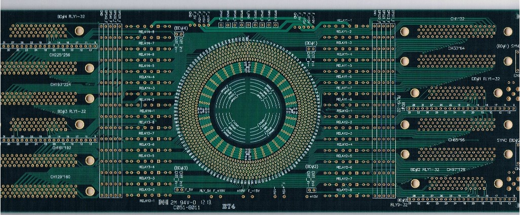
Four layers is typical for a serious instrument: a component layer, a solid ground plane, a power layer and a routing layer. The plane is what makes the rest of the design work, because it gives every fast signal a return path directly beneath it and it separates the digital switching from the analogue stage without requiring the ground to be cut in two. Splitting the ground on an audio board is a popular remedy and a frequent mistake, since it forces return currents to detour and creates the very coupling it was meant to remove.
Where the display and the amplifier share the board, the separation has to be physical as well as electrical. Switching regulators are placed away from the audio section, their inductors are oriented so that their fields do not couple into sensitive traces, and the amplifier ground returns to the supply on its own path rather than through the analogue reference. Our design release checklist places these checks in the review sequence.
Mechanical and Reliability Considerations
The board lives in a structure that moves. Keys are struck repeatedly, the sustain pedal is pressed thousands of times, and the whole assembly vibrates when the speakers are driven hard. Connectors between the keybed and the board, the ribbon cables to the panel and the jack sockets are the parts most likely to fail, and they should be mechanically supported rather than relying on their solder joints alone.
Thermal load is modest but continuous. The processor runs warm under a polyphonic load, the amplifier dissipates a few watts into the speakers, and the instrument may be left powered on for hours. Copper area beneath the processor, thermal vias into the internal planes and a clear path for air to move through the enclosure are sufficient in most designs, and our thermal management article describes how those areas are estimated.
Testing an Instrument Board
Functional test has to cover every key, every control and every output, and it has to do so quickly. A common approach is a fixture that drives the matrix electrically, simulating keypresses at known intervals, while the audio output is captured and compared against limits. That verifies the scan logic, the velocity calculation and the tone generator in a single pass.
Listening tests remain necessary because some faults are not visible in a captured spectrum. A ground noise problem, a weak contact or a slightly mis-tuned filter may pass an automated check and still be audible. The final test therefore combines measurement with a short performance check, and the instrument is played through the full key range at several dynamic levels before it is packed.
Why the Audio DSP Sets the Character
The audio DSP is where the raw note becomes an instrument. It applies the envelope that shapes the attack and the decay, runs the filter that changes with velocity, mixes the reverb and chorus that give the sound its space, and manages the polyphony so that a held chord does not steal voices from a new one. Each of those operations happens in real time, on every voice, on every sample clock, and the processing load therefore rises with the number of keys held rather than with the volume of the output.
That load has a direct consequence for the board. Memory bandwidth and supply current both peak when a sustained passage is played, which is exactly when the amplifier is also drawing its largest current. The two must not share a reference, and the regulator that feeds the digital core should be placed and decoupled so that its switching noise does not reach the converter reference. Sizing the copper beneath the DSP for the sustained load rather than the average is the difference between an instrument that behaves and one that develops a faint whine after twenty minutes of playing.
FAQ
Why does a digital piano need two contacts per key? The two contacts close in sequence as the key travels. The time between them measures how fast the key was moving, which is what produces velocity and therefore the difference between a soft and a hard note.
How many layers does a piano circuit board use? Four layers is typical for an instrument with an amplifier and a display, because the ground plane and the power plane are needed to keep digital noise out of the audio path. Simpler keyboards can use two.
What causes a single dead note on a digital piano? Usually a broken or contaminated contact in the key matrix rather than a processor fault, because each key has its own pair of switch pads. A second contact failing affects only the velocity, not the note itself.