Gaming Monitor PCB: A Complete Technical Guide
A gaming monitor is a display that has been pushed in one direction further than an office monitor: it must update faster, respond faster and stay accurate while doing so. That single emphasis changes what the board behind the panel has to deliver. The interface runs at a higher data rate, the timing controller must handle overdrive and adaptive sync, and the power and thermal design has to support the brightness and the refresh rate without the panel overheating.
What Makes the Board Different
The panel is driven by a timing controller that receives the image from the host and generates the signals the panel needs, and that controller is the heart of the board. Around it sit the input receiver, which accepts the high speed link from the graphics card, the power supply for the panel and the backlight, and an on screen display controller with its own memory.
The difference from an ordinary monitor is quantitative in the interface and qualitative in the timing. A high refresh rate multiplies the data rate, which pushes the link into the region where impedance and loss matter, and the overdrive processing that improves response time requires frame memory and a processor capable of reading and writing it fast enough to keep up with the panel.
High Speed Input and Impedance Control
The input is a differential link carrying several gigabits per second per lane, and the board must treat it as a transmission line from the connector to the receiver. Impedance is controlled to a defined value for each pair, the pairs are length matched to each other, and the reference plane beneath them is continuous. A pair that crosses a plane split is the classic cause of a link that works at sixty hertz and fails at the top of the refresh range.
Equalisation is built into the receiver, but it compensates for the channel, not for a mistake in the layout. Excess loss from long traces, from vias or from a poorly planned route shows up as a closed eye and as intermittent dropouts, and the cure is to keep the link short and direct rather than to rely on the equaliser. Where the connector is a long way from the receiver, the extra loss should be calculated before the layout is fixed. Our high frequency laminate article describes when a low loss material becomes worthwhile.
Timing, Overdrive and Adaptive Sync
Overdrive is the technique that makes a fast panel usable. The timing controller compares the previous frame with the current one and applies an overshoot voltage to pixels that are changing, which accelerates the transition. Doing that requires a frame of memory and a processor that can read it, compute the correction and write the result within one frame period, at the refresh rate, without fail.
Adaptive sync adds a second requirement: the panel’s refresh must follow the rate at which frames arrive from the host, which means the timing controller has to change its own timing dynamically. That places demands on the clock generation and on the power delivery, because a sudden change in refresh rate changes the load on the panel supply. Keeping those rails well decoupled and keeping the clock generation on its own quiet supply is what prevents the change from appearing as a flicker.
Thermal Design of a Bright Fast Panel
The backlight dominates the thermal budget. A high brightness panel requires more current through the emitters, and the heat they produce has to leave the assembly without reaching the panel itself, because the liquid crystal behaves differently when it is hot and the colour shifts. The board’s contribution is a copper area and a thermal path that conducts the heat away from the panel rather than under it.
The processing elements also dissipate. The timing controller and any scaling processor run continuously, and on a monitor that is left on for hours the internal temperature rises well above the room. Thermal vias beneath those packages, a copper area on the reverse side and a mechanical path to the chassis are the standard measures. Our thermal management article describes how those areas are sized.

EMC and Interference with the Panel
A display board is a source of interference in a confined space. The high speed link, the panel drive signals and the backlight converter all radiate, and the panel itself is a large conductive surface that can couple the interference back into the receiver. Controlling it relies on the usual measures applied carefully: continuous reference planes, short return paths, filtering at the connector and a stack-up that places the high speed layers adjacent to a solid plane.
The backlight converter deserves particular attention because its switching node drives a large loop through the cables to the emitter array. That loop is an antenna, and the cable routing inside the enclosure is part of the problem. Twisted pairs, a shielded run where necessary and a return path that runs alongside the outgoing conductor rather than through the chassis are the techniques that keep the emission within limits. Our design release checklist covers the checks that should be made before the layout is released.
Assembly and Testing
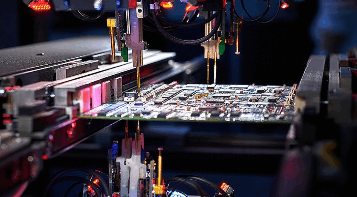
Assembly is a conventional surface mount process, though the fine pitch of the timing controller and the density of the memory interface require good stencil design and a placement machine with a vision system. The connectors for the panel and the host are mechanically loaded in service, so they should be supported by the chassis rather than by their solder joints.
Testing covers the link, the panel drive, the backlight and the on screen display, but the measurements that distinguish a gaming monitor are made optically: response time, overshoot and uniformity are measured with a photometer at the refresh rates the product supports. Testing the link at the highest data rate and at the temperature extremes is also worthwhile, because a marginal eye at room temperature closes quickly once the board is warm.
Mechanical Integration and Serviceability
A monitor board is usually mounted behind the panel on the same chassis that carries the stand and the backlight, so its mechanical design is inseparable from the rest of the product. The board should be fixed at enough points that it cannot flex when a cable is pulled, and the panel and host connectors should be positioned so that the cables run without being bent sharply against the board edge. Where the chassis is metal, it also becomes the thermal path, and the mounting points should be arranged so that heat from the processing section reaches it.
Serviceability matters more than it first appears. A monitor that must be disassembled to replace a single connector costs more to repair than the part, so the design should keep the interfaces reachable and avoid burying serviceable items under the backlight assembly. That is a mechanical decision, but it constrains where the connectors can be placed on the board and therefore how the high speed link is routed.
FAQ
Why does a gaming monitor need a different board from an office monitor? The higher refresh rate multiplies the interface data rate and the internal processing load, and the overdrive function requires frame memory and a fast processor. The board has to support all three.
What causes flicker when adaptive sync is enabled? Usually a supply rail that moves when the refresh rate changes, or a clock that is disturbed by the change. Decoupling the panel rails and giving the clock its own supply removes most cases.
Does the board affect colour accuracy? Indirectly. Heat from the electronics conducted into the panel changes the liquid crystal behaviour and shifts the colour, which is why the thermal path is designed to lead heat away from the panel rather than under it.