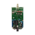
UPS Circuit Board: Structure, Function and Design
An uninterruptible power supply is a product defined by what it does in the two milliseconds after the mains fails. Everything else, the efficiency, the size, the price, is secondary to the requirement that the load never sees the interruption. The UPS circuit board is where that requirement is implemented, and its design is dominated by the transfer path, the inverter and the battery interface rather than by the control electronics that supervise them.
The Three Sections of a UPS
A UPS contains a rectifier that converts the incoming mains to a direct current, a battery that stores energy, an inverter that converts the direct current back to alternating current, and a transfer arrangement that decides what the load is connected to. In a standby design the load is normally on the mains and the inverter starts when the supply fails, which is cheap and fast enough for most equipment. In an online design the load is always on the inverter, which costs more and removes the transfer entirely, at the price of converting the power twice.
The board differs between the two. A standby unit needs a fast, reliable transfer relay or static switch and an inverter that can start into an inductive load without collapsing. An online unit needs a rectifier that draws a clean sinusoidal current, an inverter that runs continuously and a control loop that regulates the output whatever the load does.
The Rectifier, Power Factor and Charging
The rectifier in a modern UPS is an active circuit rather than a bridge of diodes, because a diode bridge draws current in narrow pulses that pollute the supply and produce a poor power factor. An active front end draws a sinusoidal current in phase with the voltage, and it also provides a regulated direct current bus that the inverter can use.
The battery charger is usually derived from that bus. It has to charge within the limits the battery manufacturer specifies, compensate the charge voltage for temperature, and switch to a float condition when the battery is full. The measurement side of the charger matters as much as the power side, because a battery that is overcharged fails early and one that is undercharged fails when it is needed. Our component tolerance and reliability notes describe how the battery connections are assessed.

Inverter Stage Layout
The inverter is a switching bridge, and its layout follows the rules of any high current switching stage with more at stake. The loop formed by the bus capacitor and the switches determines the overshoot at each switching edge and the radiated field, and it must be as small as the geometry permits. Bus capacitors are placed immediately beside the switches, connected with copper rather than with traces, and the return path runs directly beneath the outgoing path.
Gate drive needs the same discipline. The loop from the driver to the gate and back must be short, because gate loop inductance slows the switching edge and produces ringing on the gate that can damage the device. Where the bridge is spread across several packages, each device needs its own decoupling and its own return, and the bus must be a plane rather than a set of traces. Our thermal management article describes how the dissipation in the bridge is spread across the copper.

Transfer, Isolation and Safety
The transfer from mains to inverter is the moment the product exists for. A relay is simple and robust but takes several milliseconds to move, which is long enough to reset a computer; a static switch using semiconductor devices transfers in a fraction of a cycle and is used where that matters. Either way, the control circuit that decides to transfer, and the current path that carries the load, must be independent so that a failure in the control logic cannot leave the load unpowered.
Isolation is required and is not optional. Whatever the UPS output is connected to, a person may touch it, and the output must be separated from the input and from the battery. The barrier is carried across the transformers, the gate drive circuits and the measurement paths, and its physical realisation on the board is creepage and clearance distances that satisfy the applicable standard, a continuous barrier, and slots milled through the laminate where more surface distance is needed.
Thermal and Mechanical Design
A UPS dissipates in three places: the rectifier, the inverter and the magnetic components. The semiconductors are mounted on heat sinks, and the board’s contribution is to provide a low resistance path from the device pad into the sink and to keep the rest of the circuitry out of the way of that path. Where the bridge is bolted to a common heat sink, the isolation between the devices and the sink becomes part of the thermal design, because an insulating pad adds thermal resistance as well as dielectric strength.
The magnetics matter too. An inductor carrying the full output current dissipates in its winding and its core, and it is often the hottest component on the board. Its position should allow air to reach it, and its terminals should be large enough that the board does not become the limiting element in the thermal path. Our design release checklist places those checks in the review sequence.
Control, Monitoring and Testing
The control section measures the input, the output, the battery and the temperature, and it makes the decisions that keep the load supplied. Its accuracy matters more than its speed in most cases: an output voltage that is regulated to within a percent is easy, but a battery measurement that is wrong by ten percent will shorten the battery life or cause a premature transfer.
Testing of a UPS is mostly about the transitions. Transfer under full load, transfer under no load, transfer with an inductive load, recovery when the mains returns, and the behaviour of the charger across the whole battery range are all measured, along with the efficiency at part load. The test that is most often skipped is the long one: running the unit on battery until the low battery threshold is reached, at the rated load, with the temperature at the high end of the specification.
Choosing the Topology
The three common arrangements differ in what the load experiences rather than in what the electronics do. An offline or standby unit keeps the load on the mains and switches to the inverter when the supply fails, which is efficient and cheap but leaves a transfer gap that sensitive equipment may not tolerate. A line interactive unit adds a tapped transformer that corrects the voltage while the mains is present, which handles brownouts and overvoltages without using the battery at all, and it is the usual choice for small installations.
A double conversion unit runs the load from the inverter continuously and charges the battery from the rectified mains in parallel, so the load never sees the transfer. The cost is an efficiency loss of several percent, which appears as heat, and a larger, more expensive inverter. The choice is therefore made by asking what the load can tolerate, not by asking what the budget allows, and the board follows from that decision.
FAQ
Why does an online UPS cost more than a standby one? Because the power is converted twice, so the rectifier and the inverter both have to handle the full load continuously, and the efficiency loss has to be removed as heat.
Is a relay good enough for the transfer? For most equipment yes, because a relay transfers in a few milliseconds and a switch mode supply rides through that easily. Where the load is sensitive, a static switch transfers in a fraction of a cycle.
What limits the life of a UPS? The battery, almost always, and the battery life is set by its temperature and by the accuracy of the charger. Keeping the battery cool is more effective than any other single measure.