High-Speed PCB Design Rules and the Reasons Behind Them
High-speed design rules are usually presented as a list of things not to do, which makes them easy to memorise and easy to ignore. Almost every rule on the list exists for one of three reasons: controlling the area enclosed by a signal and its return path, controlling the impedance the signal sees along the way, or keeping a noisy circuit away from a sensitive one. Understanding the reason makes it possible to judge which rules matter on a particular board.
When a Board Becomes a High-Speed Board
The transition is usually defined by edge rate rather than by clock frequency. A board whose clock exceeds roughly 5 MHz, or whose rise time is shorter than about 5 ns, generally needs a multilayer stack-up. The reason is not the clock itself but the return current: at those edge rates the current follows the path of least inductance rather than the path of least resistance, and a multilayer board with a plane gives that current a path directly beneath the trace.
Where a plane is not possible, the same principle can be approximated. Critical nets on a single-layer board should be flanked by ground traces on both sides. On a two-layer board, the projection of a critical trace onto the opposite layer should sit over a large copper ground area, or the trace should be guarded and stitched in the same manner as the single-layer case.
Keeping the Return Path Underneath the Trace
On a multilayer board, route critical signals on a layer adjacent to a complete ground plane, and prefer a layer between two planes. Clock lines, buses, interface signals, radio-frequency traces, reset lines, chip selects and control lines all belong in this category. A signal routed next to a plane has a small loop area, which reduces both the radiation it produces and its susceptibility to interference.
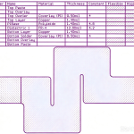
The routing layer should also lie within the projection of its return plane. If the trace extends past the edge of the plane beneath it, the return current has to spread sideways, the loop area grows and the structure radiates from the edge. For the same reason, a power plane should be inset from its adjacent ground plane by between five and twenty times the dielectric separation, a measure that suppresses edge radiation. Adjacent plane layers should not have overlapping projections, because the capacitance between them couples noise from one layer into the other.
The 3W Rule and Crosstalk
Crosstalk between parallel traces falls as the separation grows. A practical target for critical nets, including clocks, buses and radio-frequency lines, is that the centre-to-centre spacing should be at least three times the trace width, which is what the 3W rule refers to. Where the layers cannot be arranged so that no two routing layers are adjacent, run the traces on adjacent layers perpendicular to one another, or keep the parallel run shorter than about 1000 mil.
Guard traces help when a critical line has to run beside unrelated signals. A clock line flanked by ground, with the guard stitched to the plane by vias at intervals of roughly 3000 mil, holds a consistent potential along its length and provides a defined return for the coupling that would otherwise reach a neighbouring trace.
Separating Circuits by Type and Speed
Digital and analogue circuits, and high-speed and low-speed circuits, should occupy separate regions of the board. The layout should follow the signal flow in a straight line where possible rather than doubling back, so that a signal does not run alongside or across a previous stage of its own path. Mixed boards should keep the highest-speed sections furthest from the interface connectors, so that switching noise cannot couple onto an outgoing cable.
High-radiation components deserve explicit distance. Crystals, oscillators, relays and switching supplies should be kept at least 1000 mil from board-edge connectors. Sensitive circuits such as reset and watchdog sections should be kept at least the same distance from the board edge, particularly from the interface side, because an edge is where an external disturbance is most likely to couple.
Filtering, Protection and Isolation
Interface-protection and filtering components belong close to the connector, and where both functions exist, protection comes first. A protection device placed after a filter will allow the over-voltage or over-current event to destroy the filter before it is clamped. The filter components themselves should have short connections to the connector and to the local ground, and their input and output connections should not run in parallel, because coupling across the filter defeats it.
If the design uses a separate quiet ground for the interface, the filtering and isolation parts sit on the boundary between that ground and the working ground, and nothing else should be placed on the quiet ground. Bypass capacitors for an integrated circuit belong at the supply pin of that circuit, where they enclose the smallest loop, and a series terminating resistor at the source belongs at the output pin of the driving device, since moving it to the far end breaks the impedance match it is there to create.

Corners, Teardrops and Impedance Discontinuity
Right-angle and acute-angle corners are avoided because a corner changes the effective width of the trace and therefore its characteristic impedance. The discontinuity reflects energy, which appears as ringing, overshoot and radiation. Two 45-degree corners, or an arc, keep the width consistent. Where a narrow trace meets a pad, a teardrop transition avoids a sudden change in width and also improves the mechanical strength of the joint.
Corner geometry is a good example of a rule that is often applied blindly in both directions. A single 90-degree corner on a short, low-speed net will not decide whether a product passes EMC, but the same corner on a clock line inside a resonant structure can produce a measurement failure. The rule exists to protect the nets where it matters.
Power Distribution Details
The main supply plane should sit next to the ground plane to keep the supply loop small. On single and double-layer boards, a ground trace should run parallel to and immediately beside every power trace. Any component that switches a large current, such as a supply module, a fan or a relay, needs a storage and a high-frequency capacitor near its input and output terminals, so the current drawn from the supply is local rather than drawn across the board.
For high-current parts, the connection to the plane matters as much as the plane itself. A surface-mount fuse, bead, inductor or tantalum capacitor carrying more than an ampère should be connected to the plane through at least two vias, because a single via has an equivalent impedance that becomes significant at the currents and frequencies involved.
Differential Pairs and Split Planes
Differential pairs should run on one layer, with equal length and consistent spacing, and nothing routed between the two traces of the pair. The objective is equal common-mode impedance for both conductors, which is what gives the pair its noise immunity. Critical signals must never cross a split in their reference plane, including the gaps created by via keep-outs and pad antipads, because the return current then has to take a detour and the loop area increases sharply.
Where a split cannot be avoided, stitch the two reference regions together with capacitors close to the crossing point. The stitching provides a return path for the high-frequency component of the current and limits the damage the split would otherwise do. Our layer assignment guidance explains how to plan a stack-up that avoids these crossings in the first place, the high-frequency laminate notes cover material choices, and the EMI immunity material describes how these layout decisions affect measured emissions.
FAQ
Do all high-speed design rules apply to every net? No, and treating them that way makes a board unnecessarily difficult to route. The rules are aimed at nets with fast edges, high current or high sensitivity: clocks, buses, interfaces, supplies and analogue front ends. Applying the 3W rule to a slow status LED would consume area for no benefit. The engineering judgement is in classifying the nets before applying the rules.
What is the most common cause of a failed high-speed layout? A return path that is longer than the signal path. Traces crossing a plane split, signals routed past the edge of their reference plane and connectors whose ground return is a thin trace rather than a broad area all produce the same result: a small signal loop that behaves well on the bench together with a return path that radiates. Checking return continuity before checking trace length is usually more productive.
Does gopcb review these rules during fabrication review? We review the design rules that affect manufacturability and the ones whose violation cannot be corrected later, such as plane coverage under critical routing, via counts on high-current pads and spacing at the board edge. Stack-up and return-path decisions are best reviewed with the customer before release, which is why we ask for the layer assignment and the critical-net list early in the project.