Practical Notes on CVD Driver Board
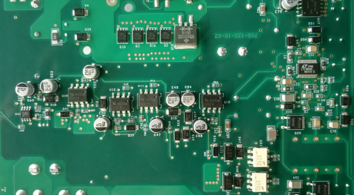
Chemical vapour deposition is a process in which a solid material is formed on a substrate from a gas phase reaction inside a vacuum chamber. The equipment that performs it is a collection of demanding subsystems: a vacuum pump, a pressure control valve, a gas delivery system with precise mass flow controllers, a heater whose temperature may exceed a thousand degrees and a radio frequency or direct current power supply that creates the plasma. The board driving all of that has to coordinate them safely and measure them accurately.
What the Driver Board Controls
The controller sequences the process, holds the setpoints and monitors the interlocks. That means it reads pressure, temperature, flow and power, drives the valves and the heater, and enforces the sequence that keeps the chamber safe. A vacuum chamber with a reactive gas supply at temperature is not a place where a sequence error can be tolerated, so the interlock logic has to work independently of the software that runs the process.
The measurement side is where the precision is needed. Pressure in a deposition chamber may be measured across six or seven decades, from atmospheric down to a fraction of a pascal, which means several gauges with overlapping ranges and a switchover that must not disturb the loop. Temperature is measured with thermocouples whose small output has to be resolved and cold junction compensated, and flow is measured by the mass flow controllers themselves, which the board reads and commands over an interface.
Power Delivery for Heaters and Plasma
Heater power can be several kilowatts, switched by a solid state relay or by a phase controlled triac, and the switching has to be synchronised with the mains so that the current is drawn smoothly. A resistive heater has a large inrush when it is cold, and the driver has to accommodate that without nuisance tripping or degrading the element.
Plasma power is generated by a radio frequency supply rather than on the board, but the board controls it and measures its output. Matching networks, which tune the impedance between the generator and the chamber, are usually automated, and the controller drives the tuning motors and reads the reflected power. What the board must do is keep the measurement of the forward and reflected power clean, because the control loop depends on it. Our component tolerance and reliability notes describe how those high power interfaces are assessed.
Vacuum Compatibility and Materials
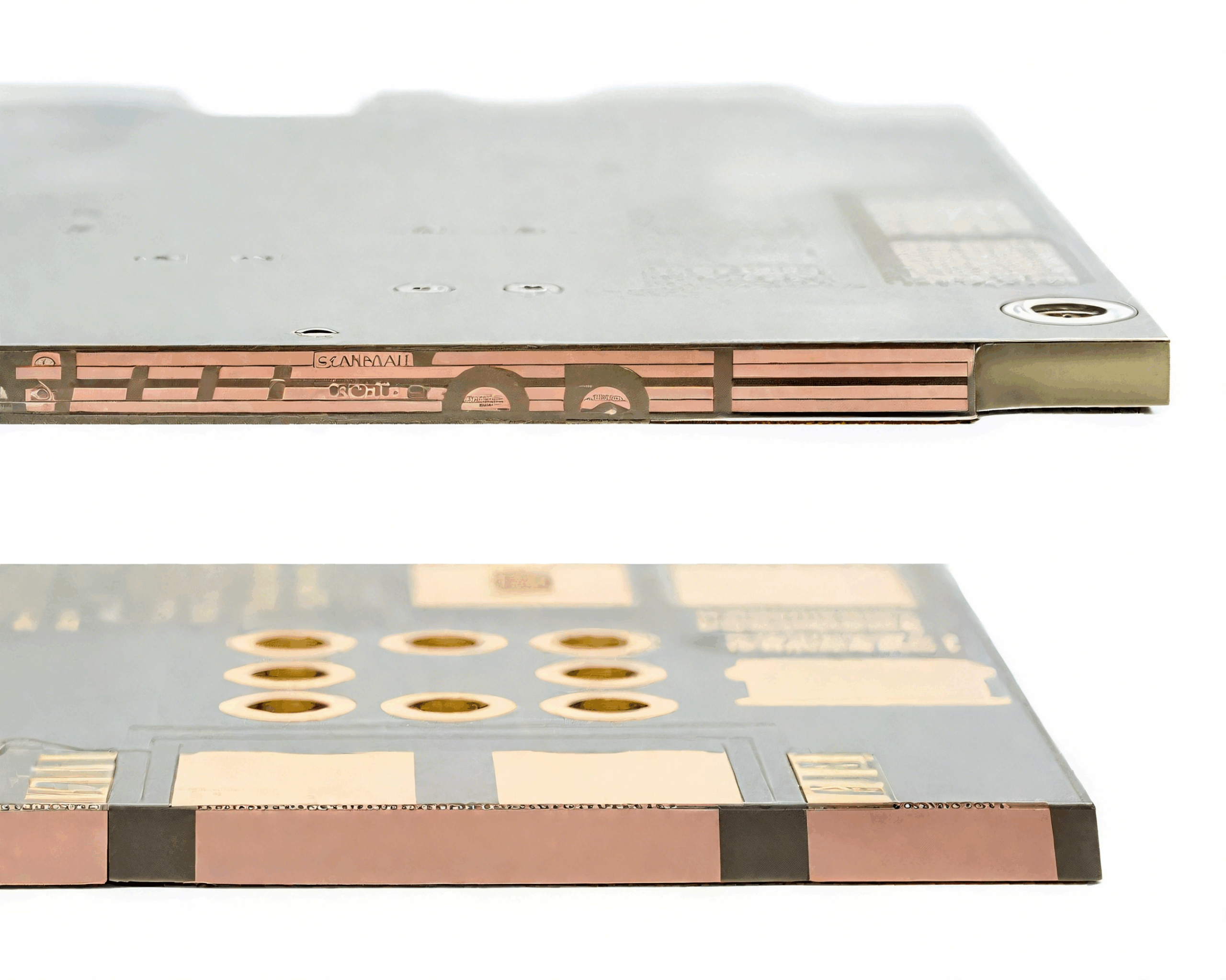
A board that is exposed to the chamber environment has to be vacuum compatible. The board itself is normally outside the chamber, but its sensors and feedthroughs are not, and anything inside must not outgas in a way that contaminates the deposited film. That is the same problem as in spacecraft hardware, and the answer is the same: low outgassing materials, low vapour pressure lubricants and a clean assembly process.
The feedthroughs that carry the signals through the chamber wall are a design element in their own right. Each one is a vacuum seal and an electrical connection, and each is a potential leak. Coaxial feedthroughs for radio frequency, thermocouple feedthroughs with matched alloys to avoid spurious junctions, and power feedthroughs with adequate current rating and insulation are all selected against the vacuum and the temperature they will see.
<img src="https://www.gopcba.com/wp-content/uploads/2026/05/HAVC-Control-System-PCBA.png" alt="vacuum feedthrough and measurement section on a deposition controller” />
Noise, Grounding and Measurement Integrity
The board sits between a multikilowatt switching power stage and a measurement system that resolves microvolts. That combination defines the layout, and the arrangements are the familiar ones applied with more discipline: a continuous ground plane, separate return paths for the high current loads and the measurement circuitry, and filtering at the point where each wire leaves the board.
The thermocouple input deserves particular care. It is a differential signal of a few tens of microvolts, referenced to the cold junction, and any common mode voltage imposed by the heater current finds its way into the measurement unless the input is isolated or the common mode is controlled. An isolated amplifier is the usual solution, and the isolation also protects the controller when a thermocouple shorts to the heater. Our design release checklist places those checks in the review sequence.
Control, Interlocks and Safety
The process cannot run unless a set of conditions is satisfied: the chamber is closed, the pressure is below a limit, the cooling water is flowing and the exhaust is operating. Those interlocks are implemented in hardware, in a chain that removes power from the heaters and the gas valves without passing through the processor, so that a software fault cannot leave the system in a dangerous state.
The processor then sequences the process on top of that foundation, and it must be able to detect a hardware interlock opening and stop cleanly rather than continue issuing setpoints to a subsystem that has been shut off. Recording the state of every interlock alongside the process data makes a failed run diagnosable, which matters when a deposition process takes hours and a batch of product is at stake.
Reliability and Service in a Fab Environment
The equipment runs continuously and its downtime is expensive, so the board is designed for reliability and for fast diagnosis. Component derating is generous, connectors are ones that can be re-mated many times, and the boards are usually in a card cage where an individual board can be replaced rather than the whole controller.
Service access shapes the mechanical design. Test points should be reachable, indicators should be visible without removing the board and the calibration constants should be stored so that a replacement board can be brought into service without recalibrating the whole system. Those are small design decisions that determine whether a maintenance call takes an hour or a day.
Gas Delivery and Flow Control
The gas system is where the process recipe becomes a physical reality, and it is the part of the equipment that most often determines whether a film has the intended composition. A mass flow controller measures the actual mass flow of a gas rather than its volume, using the thermal properties of the gas to infer the flow, and it holds that flow at the commanded value regardless of the downstream pressure. Several of them feed a manifold, and the CVD driver board commands each one and reads back the actual flow.
The interface between the board and a mass flow controller is a well defined analogue or digital one, and its accuracy depends on the reference and the return path used for the analogue signal rather than on the board’s processor. Analogue setpoints are referenced to a common ground, so that ground has to be clean and it has to be the same ground the controller uses for its own measurement, otherwise every channel is offset by a different amount and the recipe drifts between runs.
Sequence, Recipes and Traceability
A deposition run is a sequence of steps with defined ramp rates, flows, pressures and powers, and the board must execute that sequence consistently or the product will vary from batch to batch. Storing the recipe on the board and logging the actual measured values alongside the setpoints is what makes a run reproducible and what makes a failed run diagnosable after the fact.
The CVD driver board is therefore expected to record as well as to control. That has implications for the design: enough non-volatile storage for the run history, a real time clock to timestamp it, and a communication interface fast enough to transfer the data without holding up the process. Our design release checklist places those checks in the review sequence.
FAQ
Why does a deposition controller need several pressure gauges? Because the pressure range spans many decades and no single gauge covers it accurately. The gauges overlap and the controller switches between them.
Why are interlocks implemented in hardware? So that they work regardless of the software. A processor fault must not be able to defeat a safety interlock on a chamber containing reactive gas at temperature.
What is the most demanding measurement on the board? Usually the thermocouple input, because the signal is tiny and it shares an environment with several kilowatts of switching power.