
PCB Antenna Layout Considerations for Wireless Designs
A radio performs only as well as the copper that feeds it. Antenna layout decides how efficiently power leaves the board, how much of it returns as unwanted coupling, and whether the product passes certification on the first attempt. The rules are not complicated, but almost all of them are set before the schematic is finished, which is why they are so often missed.
Why the Antenna Layout Decides Range
An antenna is a resonant structure that depends on its surroundings. The same printed element that radiates efficiently on a bare evaluation board can lose most of its useful range once it sits beside a battery, a metal chassis or a plane that was extended to make routing easier. The layout fixes those surroundings long before the product is assembled.
The design target is straightforward: deliver power from the transceiver into a structure that radiates it, with as little loss and reflection as possible. Every millimetre of feed line, every nearby ground plane and every enclosure wall changes the impedance the transmitter sees. Treating an antenna layout as a footprint to be dropped in is the most common reason for a redesign.
<img src="https://www.gopcba.com/wp-content/uploads/2026/09/232-1.jpg" alt="Printed PCB antenna with a clear keep-out zone on a wireless board” />
Ground Plane Size and the Counterpoise
Small antennas work against a counterpoise, and on most products that counterpoise is the ground plane of the board itself. Its size and shape influence the resonant frequency, the bandwidth and the radiation pattern far more than most designers expect. A plane that is too small detunes the element and narrows the bandwidth; one that is asymmetric tilts the pattern.
For a module with an external antenna, the ground plane should extend beneath the module and away from the antenna, and it should be continuous on the layer nearest the antenna feed. Slots, connector cutouts and long narrow necks in the plane reduce its effectiveness as a counterpoise, so the plane under and around the radio deserves more attention than the plane elsewhere.
Keep-Out Zones and Copper Clearance
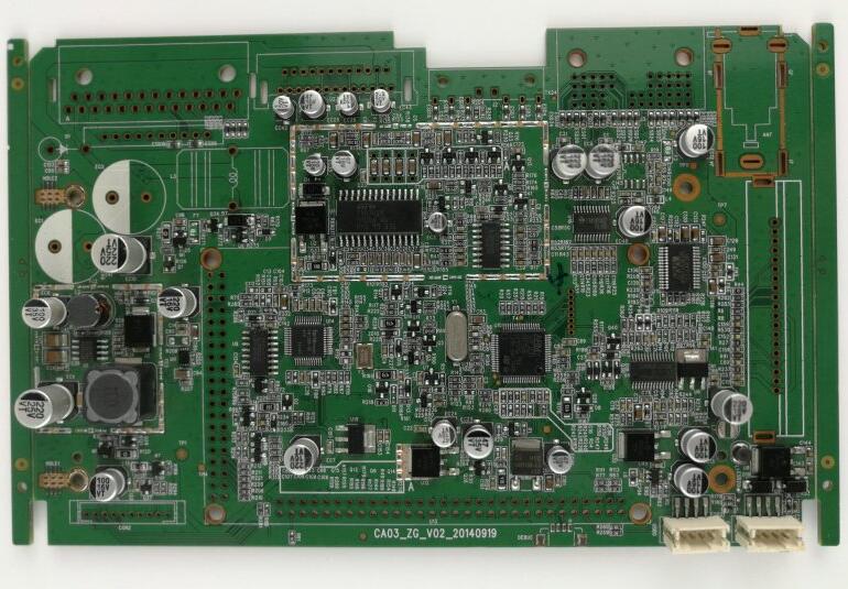
The keep-out region around a printed antenna exists for a reason: copper inside it detunes the element, absorbs radiated energy and changes the impedance. The area must be free of copper on every layer, not just the antenna layer, and it must extend far enough that the nearest plane edge does not load the radiator. Module datasheets specify the minimum dimensions, and those figures are minimums, not targets.
The keep-out also applies to components. A plastic-cased part is less harmful than a metal one, but a battery, a shield can or a metal screw close to the radiator will shift the resonance. Keep the region clear in three dimensions, and check the mechanical model as well as the artwork before signing off. Clearance rules are worth writing into the fabrication notes so they survive revision.
Feed Line and Impedance Matching
The feed line between the transceiver and the antenna should be a controlled-impedance trace, usually 50 ohm, kept as short as geometry allows. Its length is part of the matching network whether or not the designer intended it, and a trace routed over a gap in the reference plane adds inductance that the matching components then have to absorb.
A pi network of three unpopulated pads at the antenna feed costs almost nothing and saves a board revision. It allows series and shunt components to be fitted during tuning, and its position right at the feed point keeps the measurement reference clean. Impedance matching is measured with the board in its enclosure, powered as it will be in use, because cables and cases shift the result.
Module Antennas versus Printed Antennas
A certified module with its own antenna removes most of the radio design work and carries the regulatory approvals with it, provided the module is used within the conditions the certification covers. The layout rules then come from the module vendor, and the counterpoise size is usually stated as a minimum area rather than a suggested shape.
A printed antenna gives control over size, cost and appearance but leaves the tuning and the certification to the designer. It needs a laminate with predictable dielectric properties, and if the design operates at millimetre wavelengths or on a very small board, the loss of the material becomes significant. The high-frequency laminate guide explains when a low-loss material is required and when standard FR4 is adequate.
Radiation Pattern, Shielding and Nearby Metal
Radiation pattern is set by the antenna and by the ground plane, but it is disturbed by everything conductive nearby. A shield can placed over the radio compartment may be necessary for emissions compliance, yet it will also change the pattern and can reduce efficiency if it sits close to the radiator. The compromise is usually to keep the shield away from the antenna region entirely.
Display cables, batteries and metal brackets are the usual culprits. Keep them out of the near field, or accept a tilted pattern and verify it in the intended orientation. Where a switching regulator shares the board, its harmonics can desensitise the receiver, so the mixed-signal EMI guidance applies directly to the radio section as well.
Enclosure, Battery and Mechanical Constraints
Plastic enclosures shift the resonant frequency downward, typically by a few percent, and the shift depends on wall thickness and on the distance between the wall and the radiator. This is why tuning is done in the final case rather than on a bare board. A metallic enclosure changes everything, and an external antenna then becomes the practical option.
Battery placement is the constraint designers underestimate most. A cell sitting beneath a printed antenna is a large conductive mass within the near field, and it will detune the element and absorb power. Plan the mechanical stack so the antenna region is at the top or edge of the product, away from the cell and from the user’s hand.
Tuning, Measurement and Certification
Tuning requires a network analyser, a calibrated fixture and a defined reference plane. The measurement should be taken at the feed point with the board in its enclosure, at several frequencies across the band, and the result recorded as return loss or voltage standing wave ratio. A single number is not enough; the shape of the response shows how much margin remains.
Efficiency and pattern measurements need an anechoic chamber and are usually deferred to pre-compliance testing. Budget for at least one tuning iteration after the first assembled units exist. Designing the matching network as a pi pad with accessible test points makes that iteration a component change rather than a board spin.
Checklist Before Release
Confirm that the keep-out is clear on all layers, that the counterpoise meets the minimum area, that the feed line is controlled impedance and uninterrupted, and that the matching network has placeholders. Check that no metal part, cable or battery intrudes into the antenna region in the assembled product, and that the enclosure material is known.
Finally, confirm the fabrication requirements that the radio imposes: tighter impedance tolerance, a specific copper thickness, or a low-loss laminate. gopcb builds radio boards with impedance test coupons so that the controlled-impedance traces can be verified on the panel rather than assumed, which is precisely the evidence a certification lab will want to see.
FAQ
How large should the ground plane under an antenna be? Follow the module or antenna datasheet minimum, then add margin. Larger planes generally improve bandwidth, but a very large plane relative to the wavelength can change the pattern and the resonant frequency.
Can a printed antenna be tuned without a chamber? Return loss can be tuned with a network analyser and a good fixture, which is enough to reach the target impedance. Efficiency and pattern still require a chamber for meaningful numbers.
Does antenna layout affect EMC certification? Yes. A badly matched antenna reflects power back into the transmitter, and harmonics radiated from the feed line or the ground plane can push the product over the emission limits even when the radio itself is compliant.