Controlled Impedance Through Cables And Connectors
Impedance is a property of a transmission line, not of the metal in it. The energy that carries a signal at radio frequency travels in the field between the two conductors, guided by the dielectric that separates them, and it is the geometry of that arrangement which sets the impedance. Once that is understood, it becomes clear why a connector can never be treated as a simple piece of hardware.
This article looks at how a controlled impedance path behaves through cables and connectors, why a transition is the usual place a link goes wrong, and what has to be held to keep a channel working at high frequency.
The same reasoning applies at every level. A board trace, a cable assembly and a connector are all lengths of transmission line, and the system works when they all present the same impedance.
Where The Impedance Comes From
The familiar picture of electrons flowing through a conductor like water in a pipe describes direct current reasonably well and fails completely at radio frequency. What actually transfers energy is the electromagnetic field around the conductor, constrained between the centre conductor and the shield and guided by the dielectric in between. The dimensions of that structure and the properties of the dielectric, including its thickness and its permittivity, determine the characteristic impedance.
Because the impedance depends on the geometry of the field rather than on the conductor alone, changing the spacing, the diameter or the dielectric changes the impedance. That is the reason a cable is specified as a matched system and the reason a connector, which is a short section of transmission line with a transition at each end, has to be designed with the same care as the cable it terminates.

Why A Transition Causes Trouble
At low frequency a connector has one job: make a reliable contact and carry the current. At radio frequency the connector is part of the line, and every irregularity in it, whether a bump, a gap or a misalignment between the mating parts, alters the relationship between the inner and outer conductor. When the relationship changes, the impedance changes with it, and a change in impedance reflects energy back toward the source.
The reflections that return from a transition combine with the forward wave to form a standing wave, and the severity of the effect is described by VSWR. A perfect line reflecting nothing has a VSWR of one to one. A badly designed connector or a poor crimp raises it, and the consequences are distortion, lost power and, in high power systems, damage to the hardware itself.
Manufacturing Precision And Passive Intermodulation
If the field is controlled by geometry, then connector manufacturing is a precision exercise. At microwave and millimetre wave frequencies a small dimensional error or an uneven surface has a disproportionate effect. This is where passive intermodulation becomes significant: an interfering signal generated by microscopic defects, contamination or dissimilar metals in the signal path, rather than by an active device.
The remedy is process discipline. Cleaner, more consistent contact surfaces produce lower passive intermodulation, which is why a high performance connector goes through controlled machining, plating and inspection. It is also why installation matters so much: a loose connector or a contaminated interface will undo the precision that was built into the part.
Insertion Loss Adds Up
Even a connector with an excellent VSWR and low passive intermodulation contributes insertion loss, the fraction of the signal power absorbed as it passes through. Conductor resistance, dielectric absorption, radiation and the small mismatches that remain in any real design all take a share. A single connector may cost only a small fraction of a decibel, but the losses accumulate along a chain, and a long link with several connectors can lose meaningful power before the signal reaches the receiver.
Minimising insertion loss is therefore a system level exercise rather than a component level one. Every additional joint, adapter and length of cable adds to the total, and the design decision that removes a transition is usually worth more than a marginal improvement in one component. Choosing the right transmission line structure on the board is part of the same accounting.
Shorter Wavelengths, Tighter Tolerances
As frequency rises the wavelength falls, and the physical size of everything in the path has to fall with it. Features that are irrelevant at low frequency become design variables at high frequency, and dimensional tolerances tighten accordingly. This is the pressure that shaped the connector families used in modern radio equipment, and it applies equally to the board: the launch from the connector to the trace is a transition like any other.
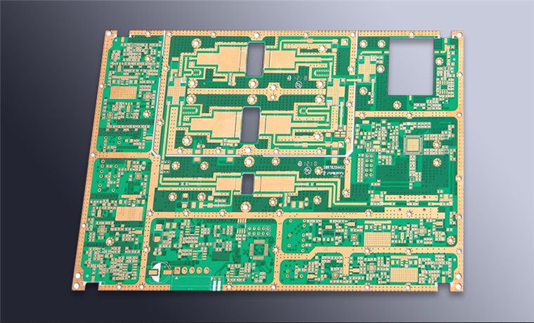
The board end of the path deserves the same attention as the cable. A connector footprint that does not preserve the impedance, a ground plane that is interrupted under the launch, or a route that turns too sharply will all introduce reflections that no amount of cable quality can correct. The suppression of unwanted coupling belongs in the same conversation, because a leaky launch radiates as well as reflects.
Assembly And Handling
A connector that is correct in design can still behave badly once it is installed. The crimp or solder joint sets the geometry at the cable end, and a joint with the wrong amount of metal or a shield that is not fully dressed becomes a small discontinuity of its own. Torque matters for the same reason, since a coupling that is not fully tightened leaves a gap in the outer conductor where the field is no longer contained.
Handling is the other half of the story. A scratched plating, a bent centre contact or a connector that has been mated too many times all degrade the interface, and the degradation is progressive rather than sudden. Where a link has to be reliable over years, the assembly procedure and the number of mating cycles belong in the specification alongside the electrical figures.
It is also worth remembering that a connector specification describes a new part, and that the behaviour that matters is the behaviour after a few hundred cycles in a real installation. Testing a link in the state it will actually be in is a more useful exercise than measuring a sample that has never been mated.
A System Level Discipline
Controlling impedance well means treating the whole path as one continuous transmission line, from the board launch through the connector, the cable and the antenna. The material, the geometry, the plating and the assembly all affect how the energy travels, and a matched system is one in which each part behaves as a section of the same line rather than as a component with its own characteristics. gopcb builds boards for RF and high speed products with documented stackups and verified impedance, so that the board end of the path is not the part that lets the system down.
FAQ
Why is fifty ohms the usual reference? It is a compromise between the lowest loss and the highest power handling for an air spaced coaxial line, and it became standard through decades of use.
Can a good cable compensate for a poor connector? No. The connector is part of the line, and its reflections add to those from everything else in the path.
Does passive intermodulation matter at low power? It matters less, because the interfering products scale with the power passing through the junction. In a high power transmit path it is a primary concern.