
SMT Placement Machine Faults and How to Trace Them
When a placement machine begins placing parts off centre, rotating them or dropping them altogether, the first instinct is to edit the program. Most of these faults originate in the machine, the board support or the feeder, and a disciplined sequence of checks finds the cause faster than any change of offset.
Start With the Sequence
Each cycle is a chain: the feeder presents a component, the nozzle picks it, the head travels, the vision system measures it and the head places it. A fault belongs to one link of that chain, and identifying the link removes most of the guesswork.
Write the sequence down and follow it while the machine is stopped. A part lost between the pick and the place is a different fault from one that is measured correctly and then placed in the wrong position, even though both look like a misplaced component.
Questions That Narrow the Fault
Where did it happen: at one head, one nozzle, one feeder position, or across the whole machine? Was it a single part number or every part in the program? Did it begin after a changeover, at a particular time of day, or with one batch of boards?
The answers point at different causes. A fault tied to one nozzle is mechanical, a fault tied to one batch is material or board related, and a fault that follows a single head is unlikely to come from the program, which is shared by every head.
Offset in X and Y
A consistent offset in one direction usually traces back to the board rather than the machine. Warpage beyond the working tolerance, support pins set at different heights, or a table that is not flat will tilt the board so that every placement lands slightly off target.
If the offset follows a nozzle instead, inspect the nozzle bore and the pickup height. A worn nozzle picks the part at a slight angle, after which the vision system measures and places it accurately in the wrong frame of reference.
Rotation Errors
A part placed with an angular error is most often a nozzle fault: a worn or blocked tip, a poor fit between the nozzle and the component, or a parallel error between the nozzle unit and the table. Contamination on the tip has the same effect.
Vision adds its own failure mode. If the camera is loose, or if the initial recognition data is wrong, the machine will rotate the part to correct an error it has misread, which produces a rotation that no mechanical adjustment can remove.
Components Lost Between Pick and Place
Parts that disappear during travel point at the vacuum rather than the mechanics. A pickup pressure below about 400 mmHg, a nozzle partly blocked by dust, or a blow-off that fires before the head has descended will release the part in mid air.
Check the timing as well as the level. A blow-off pulse that overlaps the descent of the head, or a vacuum that is switched off too early, produces exactly the same symptom as an inadequate vacuum and is often missed during a pressure check.
Pick Failures at the Feeder
If the nozzle returns empty, the fault is usually at the feeder. Tape width that does not match the feeder specification, a cover tape that has not peeled, or a sprocket that does not advance cleanly will all leave the component out of reach of the nozzle.
Also confirm the pick height. If the nozzle does not descend far enough, or if the component thickness data is wrong, the tip will sit above the pocket and the vacuum will pull air rather than a part, which looks like a vacuum fault but is a data fault.

Random Misses and Posture Faults
A placement that is simply not made, while the machine reports no error, is often a stopper or cylinder that has not returned to position. The fault is intermittent because the mechanism only fails when a cycle follows immediately after another one.
Parts that stand on edge or lean come from a different set of causes: pickup height, component thickness in the data, tape pockets that are too large, or a feeder centre line that does not align with the nozzle axis. The part is picked correctly but held badly.
Board Support and Warpage
Board curvature is a common root cause of both offset and random misses. An upward bow of about 1.2 mm or a downward bow of roughly 0.5 mm is enough to change the placement height, and a support pin that is a fraction too high tilts the panel across the whole cycle.
Support tooling has to match the panel, not the machine. Panels that are panelised with breakaway rails, or that carry heavy copper on one side, need support positions chosen for the actual board rather than the default pin layout.
Maintenance That Prevents Recurrence
Most of these faults return because the underlying wear was never addressed. Nozzle bores, O-rings, filters and feeder sprockets belong on a scheduled inspection, and the spare parts should be on site before a production run rather than ordered after a failure.
Logging matters as much as hardware. Recording which head, nozzle and feeder produced a reject turns a random defect into a trend, and a trend can be fixed during planned downtime instead of during a customer order.
Process Control and Verification
On a design of this kind, vacuum is the item that decides how the rest of the board is arranged. Where the requirement is not written down, the shop supplies its own default, and the default is chosen for the process rather than for the design. The measurements that matter are the repeatable ones: conductor width and spacing, annular ring, finished hole size, plating thickness and surface finish are all verifiable on a coupon that travels with the panel.
Running a first article through the same checks as the production panel confirms that the two agree, and that comparison is the cheapest form of process control available at prototype stage. Keeping a sample from the panel turns a dispute into a measurement, because the same coupon can be re-examined by both parties without rebuilding the batch.
Related reading: our fabrication notes, board quality and design release notes cover the same ground.
Process Control and Verification
On a design of this kind, vacuum is the item that decides how the rest of the board is arranged. Where the requirement is not written down, the shop supplies its own default, and the default is chosen for the process rather than for the design. The measurements that matter are the repeatable ones: conductor width and spacing, annular ring, finished hole size, plating thickness and surface finish are all verifiable on a coupon that travels with the panel.
A first article check confirms that the process and the drawing agree on the points listed above, and that the coupon data supports the values used in the design.
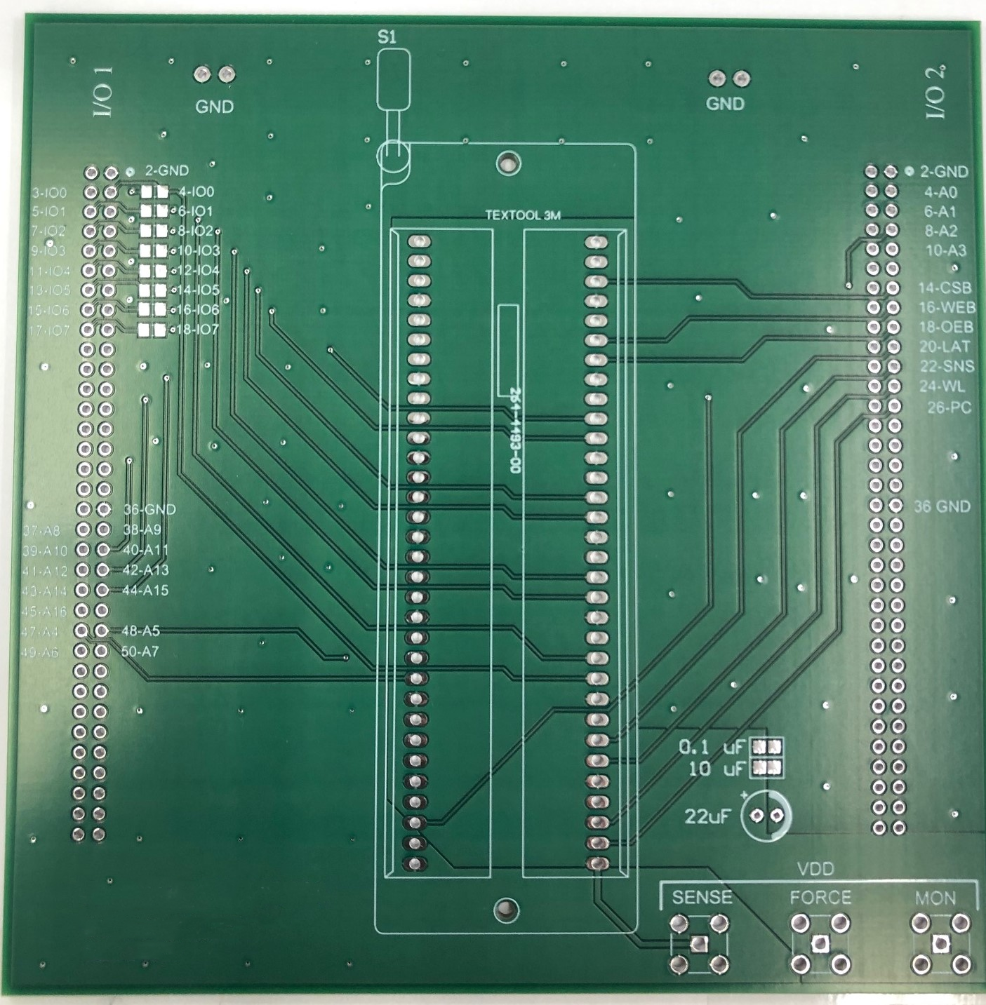
Where a measurement falls outside the expected window, the sample is retained so that the cause can be established before the balance of the batch is released.
FAQ
Why does the same fault keep coming back after adjustment? Because the adjustment treats the symptom. Check the nozzle, feeder and support tooling for wear before changing the program data.
Should I correct a placement offset in the program? Only after the board, support pins and nozzle are known to be good. Otherwise the correction hides a mechanical fault until it becomes larger.
What vacuum level is needed? Pickup and placement generally need more than 400 mmHg at the nozzle, measured at the tip rather than at the pump.