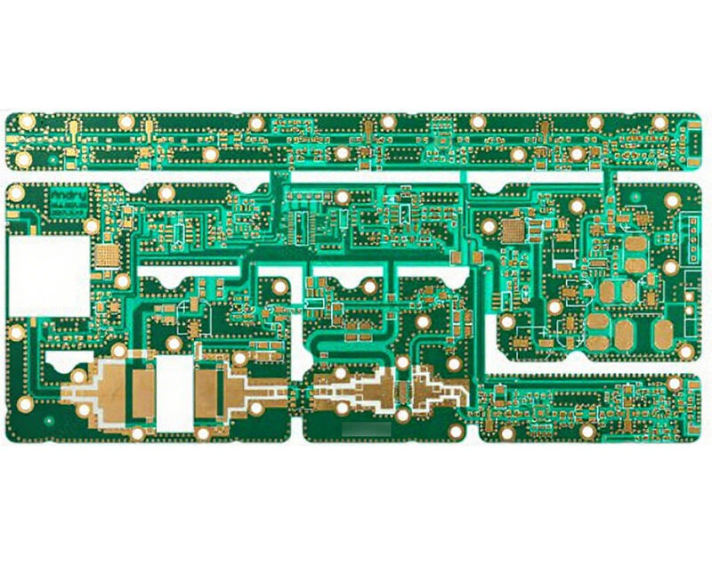
Input Protection: Reverse Polarity, Surge and Overvoltage
Anything connected to a product by a user is a potential source of damage to it. Input protection is the set of parts that stand between the outside world and the circuit, and it is frequently the set of parts that receives the least analysis.
Reverse Polarity
A supply connected the wrong way applies the full voltage across the circuit in reverse. A series diode blocks it and costs a forward voltage drop and the heat that goes with it.
A diode in parallel with the input, arranged so that it conducts when the polarity is reversed, shorts the supply and blows the fuse. It costs nothing in normal operation and it requires the fuse to be rated for the fault.
A P channel transistor arrangement blocks the reverse voltage with a much smaller loss than a diode. It costs more and it is the right answer where the current is high and the efficiency matters. Our component selection notes describe the parameters used.
Overvoltage
A transient voltage suppressor clamps the input voltage above the normal range and below the damage threshold of the circuit. Its placement and its return path determine its effectiveness.
The standoff voltage must exceed the maximum normal input, including any ripple and any load transient overshoot, or the device conducts in normal operation and fails.
The energy rating must exceed the transient energy. Where the source can deliver a large surge, a varistor handles more energy than a diode and clamps less precisely. The two are sometimes combined, with the varistor absorbing and the diode clamping. Our EMI immunity notes describe the related filtering.

Surge and Its Return Path
A surge is a short, high energy transient with a defined waveform. The protection must divert it before it reaches the circuit, which means the device must be at the input.
The return path is as important as the device. The surge current must reach the reference through a short, wide conductor, and the inductance of that path determines the voltage that appears across the circuit during the event.
A common mistake is to place the protection device on one side of the board and the fuse on the other, so that the surge current flows across the board before it is diverted. Both should be at the connector. Our industrial assembly notes describe the input arrangement used for control equipment.
Coordination and the Fuse
The protection device and the fuse must work together. The fuse must carry the normal current and must not operate during a clamp that the device survives.
Where the fuse is slow, the device must absorb the surge energy alone. Where the fuse is fast, it may open during a normal inrush and leave the circuit without protection.
The coordination is checked on the curves: the fuse’s time current characteristic against the device’s energy rating at the transient current. Our design release checklist notes where the coordination is recorded.
Inrush and the Capacitive Load
An input with a large capacitor draws a large current at switch on. The protection must tolerate it and the fuse must not open.
A soft start circuit limits the inrush by ramping the input or by adding a series element that is bypassed after the capacitors are charged.
Where the input is switched by a connector, the inrush can be high enough to damage the connector contacts. The contact rating must accommodate the inrush rather than only the steady current.
Filtering and Protection Together
A filter at the input and a protection device at the input occupy the same space, and their order matters. The protection should be first so that it clamps before the filter elements see the transient.
The filter’s series element adds impedance that limits the current into the protection device, which changes the coordination.
Both must have short returns to the connector ground for the same reason: the inductance of the return path limits the frequency at which either is effective.
Verification
The verification is an injection test at the input, with the specified surge waveform, at the maximum energy the standard requires, with the circuit operating.
The measurement should be made at the input of the protected circuit and not at the connector, since the residual is what matters.
The test should also confirm that the protection survived: a device that conducted and failed may go open, leaving the circuit unprotected for the next event. Our quality notes describe the checks after the injection.
Process Control and Verification
On a design of this kind, coordination is the item that decides how the rest of the board is arranged. Where the requirement is not written down, the shop supplies its own default, and the default is chosen for the process rather than for the design. The measurements that matter are the repeatable ones: conductor width and spacing, annular ring, finished hole size, plating thickness and surface finish are all verifiable on a coupon that travels with the panel.
Running a first article through the same checks as the production panel confirms that the two agree, and that comparison is the cheapest form of process control available at prototype stage. Keeping a sample from the panel turns a dispute into a measurement, because the same coupon can be re-examined by both parties without rebuilding the batch.
Reviewing the design before the data is released is cheaper than correcting it after the panel is in the tank, because every step downstream inherits the decision made at the front end. Documenting the assumption is part of the design work, and a short note on the drawing prevents a question that would otherwise arrive a day later and cost a day of schedule.
Process Control and Verification
On a design of this kind, coordination is the item that decides how the rest of the board is arranged. Where the requirement is not written down, the shop supplies its own default, and the default is chosen for the process rather than for the design. The measurements that matter are the repeatable ones: conductor width and spacing, annular ring, finished hole size, plating thickness and surface finish are all verifiable on a coupon that travels with the panel.
Running a first article through the same checks as the production panel confirms that the two agree, and that comparison is the cheapest form of process control available at prototype stage.
Process Control and Verification
On a design of this kind, coordination is the item that decides how the rest of the board is arranged. Where the requirement is not written down, the shop supplies its own default, and the default is chosen for the process rather than for the design. The measurements that matter are the repeatable ones: conductor width and spacing, annular ring, finished hole size, plating thickness and surface finish are all verifiable on a coupon that travels with the panel.
FAQ
Is one protection device enough? Where the transient energy and the circuit’s rating allow, yes. Where the input is exposed to a severe environment, several coordinated stages are used.
Does a series diode protect against surge? It blocks reverse polarity and does nothing for a positive transient.
What does gopcb provide for input protection? We provide device selection for the standoff, energy and clamping requirements, placement and return path design at the connector, coordination with the fuse, inrush limiting, and injection testing at the specified waveform.