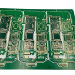
Land Pattern Design: Pads, Fillets and Density Levels
The land pattern is the copper the component sits on. It decides how much solder forms the joint, how much the component can move, and how much of the joint an inspector can see. It is defined once and then inherited by every board that uses the part.
What the Land Pattern Controls
The pad length and width set the volume of solder that can form the fillet. Too little produces an open or a weak joint; too much produces bridging and tombstoning on small parts.
The pattern also sets the self-alignment during reflow. A part that is placed slightly off centre is pulled into position by the surface tension of the molten solder, and that pull only works if the pads are symmetric and correctly sized.
Density Levels
Published standards define density levels that trade the amount of solder joint against the space the part occupies. The most generous level suits hand assembly and rework; the tightest suits dense boards where inspection is by machine.
The level should be chosen per product rather than per library. A board that mixes an aerospace power section with a dense digital section may legitimately use two levels, and the drawing should say which applies.
Toe, Heel and Side Fillets
The toe fillet carries the inspection and often the thermal load. The heel is where the stress concentrates when the board bends. The side fillets add strength but are the first to be lost when the pad is too narrow.
A pattern with a good toe and a poor heel passes a visual inspection and fails in thermal cycling, which is why the joint should be judged against the intended use and not only against a picture.

Solder Mask and Paste Apertures
The mask opening is usually larger than the pad, and the difference is the mask expansion. Too small and the mask sits on the pad and blocks the joint; too large and the mask web between fine pitch pads disappears.
The paste aperture is not always the same as the pad. Paste is reduced on thermal pads and on fine pitch, and it is increased where the joint needs more volume. Our solder paste volume notes cover how the reduction is set.
Thermal and Ground Pads
A pad connected to a ground plane conducts heat away from the joint during reflow. The pattern must therefore be split or the plane relieved, otherwise the joint forms late and the solder does not reach temperature with the rest of the board.
The vias in a thermal pad must be filled or tented, or the paste wicks into them. That loss of volume is a common cause of voids that appear unrelated to the pattern itself. Our paste inspection notes show how the volume is verified.
Courtyard and Placement
The courtyard is the keep-out that guarantees the part and its neighbours can be placed and reworked. A design that ignores it assembles in the prototype and fails when a second source or a larger replacement part is used.
Placement tolerance should be checked against the courtyard rather than against the pad, because the part can be perfectly on the pads and still leave no room for a nozzle or a rework tool.
Verification
The pattern should be verified against the component drawing before the first order, and against the assembled joint after the first build. The two checks catch different mistakes.
The assembled check looks at the fillet height, the position, and the voiding. Our AOI notes describe how the optical check is programmed and what it can and cannot see.
Process Control and Verification
Reviewing the design before the data is released is cheaper than correcting it after the panel is in the tank, because every step downstream inherits the decision made at the front end. Documenting the assumption is part of the design work, and a short note on the drawing prevents a question that would otherwise arrive a day later and cost a day of schedule.
The process window is set by the narrowest step in the flow, so an improvement anywhere else shows up as margin rather than as yield until that step is addressed. A short note on the drawing about handling, storage or packaging is often worth more than an extra decimal place on a tolerance.
Where a value sits close to a process limit, the drawing should say so, since the shop can then open the process window rather than working to a nominal figure that carries no tolerance.
Checks Before Release
The checks that matter are the ones performed on the product rather than on a sample kept for the purpose, because a coupon that travels with the panel is the only evidence about that panel. Where a requirement can be measured, it should be measured at the point of manufacture and recorded against the board or the lot it applies to.
A parameter that is set once and never re verified drifts, and the drift is usually discovered by a defect rather than by the record. The tooling, the material and the profile form one system, and a change to any of them should be assessed against the other two before it is released.
Where the process window is narrow, the measurement resolution has to be better than the window, or the data cannot distinguish a good part from a marginal one. A record that identifies the operator, the date and the settings is worth more than a record that identifies only the result.
Verification and Records
The acceptance criteria should be written before the work starts, so that the decision is made by the specification rather than by the person inspecting. Where an operation cannot be verified afterwards, it has to be controlled during the operation, and that control has to be visible in the record.
Sampling is a compromise between cost and confidence, and the sample size should follow from the failure rate that has to be detected.
FAQ
Should the pad be larger than the component termination? Yes, by an amount that leaves a fillet at the toe and the heel. A pad exactly the size of the termination gives no fillet and no process window.
Can one land pattern serve all products? It can serve products with the same assembly process and the same inspection method. Mixing hand assembly with dense machine assembly in one library usually forces a compromise that fits neither.
What does gopcb provide for land patterns? We provide pattern selection against the component drawing and the assembly process, density level definition, mask and paste aperture sizing, thermal pad and via treatment, courtyard verification, and joint inspection after the first build.