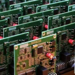
Radiation Detector Circuit Design With a Geiger Tube
A radiation detector built around a Geiger tube is a small system with three difficult parts: generating a stable high voltage from a battery, shaping a very small pulse without losing it in noise, and converting a count rate into a dose rate that can be trusted.
What the Detector Has to Do
The instrument measures the rate at which ionising particles pass through the tube and converts that rate into a dose rate for display. The count rate is a statistical quantity, so the display has to be averaged over a defined interval.
The requirements are a wide dynamic range, a low quiescent current for battery life and a housing that keeps the high voltage away from the user. The measurement chain is short, and each stage contributes to the accuracy of the result.
How a Geiger Tube Works
The tube is filled with a gas at low pressure and has a cathode and an anode held at a high voltage. An ionising particle creates a discharge that is quenched by a small amount of halogen or organic gas, producing a current pulse.
Each pulse represents one event, and the amplitude is largely independent of the energy of the particle. That independence is the reason the tube counts events rather than measuring energy, and it is why a filter is used when a dose rate is required.

The High Voltage Supply
The tube needs a few hundred volts, and it takes very little current. A boost converter followed by a diode multiplier in the Villard or Cockcroft Walton arrangement produces the voltage from a low input with a small component count.
The output has to be regulated, because the plateau over which the tube counts correctly is finite. A supply that drifts with temperature or battery voltage will change the count rate and produce a reading that drifts with it.
Limiting and Protection
A series resistor between the supply and the tube limits the current when the tube conducts, and it also provides the voltage pulse that the first stage amplifies. Its value is a compromise between the amplitude of the pulse and the recovery time of the tube.
The high voltage has to be protected from the outside world. A protective resistor at the sensing connection and a spark gap are worth the cost, because a discharge through the front end destroys the transistor that receives the pulse.
The Pulse at the Electrode
The discharge pulls the electrode down by tens of volts in less than a hundred nanoseconds. That fast edge is the signal, and it has to be coupled to the amplifier without the parasitic capacitance of the high voltage path spoiling it.
Where the tube is connected with a negative high voltage, the pulse is taken from the cathode and the coupling capacitor can be avoided altogether. That arrangement removes a component from the high voltage path and improves the shape of the pulse.
The Analog Front End
The first stage buffers the pulse, the second amplifies it to a logic level, and a comparator with hysteresis converts it into a clean edge for the counter. The bandwidth matters more than the gain, because the pulse is short.
Noise immunity is the design problem. The comparator threshold should be set above the noise floor but below the smallest pulse the tube produces, and the reference should be filtered so that the supply ripple does not create false counts.
Discrimination and Counting
The comparator output drives a counter, either in hardware or in a timer input of the microcontroller. The discriminator removes the low level noise that would otherwise be counted as an event.
The threshold setting is verified with a known source rather than by inspection. A threshold that is too low produces a background reading that is too high, and one that is too high loses real counts and under reads the dose.
Dead Time and Counting Loss
After each discharge the tube cannot respond for a short period, so the count rate is not linear at high rates. The measurement has to be corrected for that dead time, or the instrument will under read exactly where the reading matters most.
The correction is a calculation in the firmware using the measured count rate and the dead time from the datasheet. The result should be verified against a known source at the top of the range.
Calibration
The conversion from counts to dose rate, or to a reading in the units the instrument displays, is a scale factor that depends on the tube, the energy of the source and the filter. It is established with a calibrated source and stored in the instrument.
The sensitivity to energy is a limitation of the method. A tube responds differently to different photon energies, so a factor that is correct for one source is approximate for another. That limitation is stated in the product documentation rather than hidden.
Power and Battery Life
The high voltage converter, the display and the processor dominate the consumption. A converter that runs continuously draws more than the measurement requires, so it is switched on for the measurement interval and off between them where the tube allows.
The display is often the largest consumer. A monochrome display with a low duty backlight and a short timeout makes more difference to the battery life than any change in the analog front end.
Layout and Noise
The high voltage section is a noise source and a safety hazard in the same area. Its loop should be small, its components spaced for creepage, and the analog input of the amplifier kept away from it.
The techniques are those of any switching converter layout, with the addition of the high voltage clearances. Where the converter is a boost, its emission also has to be considered under EMI suppression and the conductors dimensioned with the usual current capacity rules.
Production Test
Each unit is tested for the high voltage, the background count rate and the response to a source. The background rate is the most useful test, because it is sensitive to almost every fault in the chain.
The high voltage is measured through a divider probe rather than by contact, and the reading is recorded. A unit with the correct count rate but the wrong voltage will drift in the field, and the record is what makes that visible.
Process Control and Verification
On a design of this kind, calibration is the item that decides how the rest of the board is arranged. A short note on the drawing about handling, storage or packaging is often worth more than an extra decimal place on a tolerance. Where a value sits close to a process limit, the drawing should say so, since the shop can then open the process window rather than working to a nominal figure that carries no tolerance.
FAQ
Why is the pulse amplitude independent of energy? Because the tube operates in the Geiger region, where the discharge is the same for every event. The information about energy is lost.
What limits the count rate? The dead time of the tube. Above a certain rate, events arrive during the recovery period and are not counted, so the reading has to be corrected.
Can the instrument be calibrated without a source? Only approximately. A traceable source is what turns a count rate into a dose rate that can be compared with a reference.