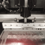
Through-Hole Lead Forming, Seating and Trimming
Through-hole parts are still used where the mechanical strength, the current or the connector family requires them. Their leads have to be formed to fit the hole spacing and then trimmed, and the way those two steps are done decides whether the part sits flush and whether the joint is reliable.
Why the Lead Is Formed
The lead is bent so that the spacing matches the holes and so that the body stands at the intended height above the board. Forming also provides a strain relief that keeps the solder joint from carrying the mechanical load.
A formed lead with a stress relief bend absorbs movement. A lead that goes straight into the hole transfers every movement into the joint. Our reliability notes describe how the load path is assessed.
Forming Tools and Damage
The lead should be formed with a tool that supports the lead where it leaves the body. Bending a lead by hand against the body damages the seal and, in a glass sealed part, cracks it.
The bend radius has a minimum, and the distance from the body to the start of the bend has a minimum as well. Both come from the component data rather than from convenience.
Lead Length and Trimming
The lead length below the board is set by the soldering method. Wave soldering needs enough lead to form a fillet, and the excess is trimmed afterwards; selective soldering and hand soldering allow a shorter protrusion.
Trimming after soldering loads the joint. The cutter should support the lead and the joint, and the operation should be done with a tool that shears rather than pulls. Our joint defects notes describe the damage that follows.

Seating and Flushness
Some parts must sit flush: a connector that mates with a panel, a part with a heatsink interface, or a standoff. Forcing a part flush against a formed lead stresses the joint before the board is even tested.
Where flush mounting is required, the lead spacing should match the hole spacing exactly and the lead should be formed with a short stress relief that still allows the body to sit down.
Hole Fit
The hole diameter must clear the lead with enough room for the plating and for the solder to rise. Too tight and the part cannot be inserted without force; too loose and the joint needs more solder than the fillet provides.
The annular ring must survive the drilling and the insertion, which is why the hole and pad sizes are chosen together. Our hole types notes describe how the two are specified.
Hand Assembly and Machine Assembly
Machine insertion requires the leads to be formed to a defined geometry so that the tool can grip and drive them. Hand assembly tolerates more variation and produces more of it.
Where both are used on the same board, the forming specification must serve both, or the parts inserted by machine will not match the ones inserted by hand. Our fabrication notes notes list the attributes that should be stated.
Verification
The check is the seating height, the lead protrusion and the condition of the lead where it leaves the body. All three are visible before soldering and none of them can be corrected afterwards.
A sample should be measured against the drawing rather than judged by eye, because the difference between a part that is seated and one that is nearly seated is small. Our quality notes describe how the result is recorded.
Additional Considerations for This Build
Practical attention to lead forming pays for itself here, because it decides whether the finished board behaves as the drawing intended. Where the requirement is not stated on the fabrication drawing or in the assembly notes, the shop has to assume a default, and that default is rarely the value the design was simulated with. Stating lead forming explicitly, together with the tolerance that applies, removes the assumption and keeps the result predictable from batch to batch.
Process Control and Verification
On a design of this kind, trimming is the item that decides how the rest of the board is arranged. Keeping a sample from the panel turns a dispute into a measurement, because the same coupon can be re-examined by both parties without rebuilding the batch. Reviewing the design before the data is released is cheaper than correcting it after the panel is in the tank, because every step downstream inherits the decision made at the front end.
Documenting the assumption is part of the design work, and a short note on the drawing prevents a question that would otherwise arrive a day later and cost a day of schedule. The process window is set by the narrowest step in the flow, so an improvement anywhere else shows up as margin rather than as yield until that step is addressed.
A short note on the drawing about handling, storage or packaging is often worth more than an extra decimal place on a tolerance. Where a value sits close to a process limit, the drawing should say so, since the shop can then open the process window rather than working to a nominal figure that carries no tolerance.
A stack-up that is drawn rather than described removes most of the ambiguity from a quotation, and it lets the fabricator price the board against the dielectric and copper weights that will actually be used.
Process Control and Verification
On a design of this kind, trimming is the item that decides how the rest of the board is arranged. Keeping a sample from the panel turns a dispute into a measurement, because the same coupon can be re-examined by both parties without rebuilding the batch. Reviewing the design before the data is released is cheaper than correcting it after the panel is in the tank, because every step downstream inherits the decision made at the front end.
Documenting the assumption is part of the design work, and a short note on the drawing prevents a question that would otherwise arrive a day later and cost a day of schedule.
Process Control and Verification
On a design of this kind, trimming is the item that decides how the rest of the board is arranged. Keeping a sample from the panel turns a dispute into a measurement, because the same coupon can be re-examined by both parties without rebuilding the batch. Reviewing the design before the data is released is cheaper than correcting it after the panel is in the tank, because every step downstream inherits the decision made at the front end.
A first article check confirms that the process and the drawing agree on the points listed above, and that the coupon data supports the values used in the design.

Where a measurement falls outside the expected window, the sample is retained so that the cause can be established before the balance of the batch is released.
FAQ
Should leads be trimmed before or after soldering? After, in most processes, so that the fillet forms on a lead that is still supported by the fixture. The trimming method then has to avoid loading the joint.
Can a lead be bent more than once? No. A second bend on the same lead work hardens it and often cracks the seal, and the part should be replaced instead.
What does gopcb provide for lead preparation? We provide forming geometry with the stress relief and bend radius from the component data, form tooling that supports the lead at the body, lead length and trimming method by soldering process, hole fit and annular ring definition, seating height verification, and first article measurement against the drawing.