Feeder Setup, Tape and Reel Verification
The feeder is where the component enters the process, and its setup decides whether the placement program sees the part where it expects it. Most “placement” defects are feeder defects.
What the Feeder Does
The feeder advances the tape by one pocket each time it is indexed and presents the part at the pick position. The position depends on the tape pitch, the pocket size and the feeder calibration.
A feeder that is not calibrated presents the part offset by a fraction of a millimetre, and the nozzle picks it off centre or misses it. Our placement accuracy notes describe how the offset appears in the data.
Tape and Reel Conditions
The tape must match the feeder pitch and the pocket must be the right size for the component. A part that moves in an oversized pocket arrives at the pick point in a different position each time.
The cover tape peel force should be within the range the feeder can handle. A tape that peels too easily opens before the pick; one that is too stiff stalls the feeder. Both appear as missing parts. Our component storage notes describe the conditions that change the tape behaviour.
Reel and Splicing
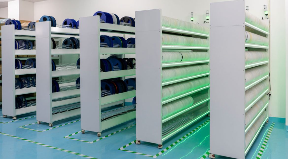
The reel should be the size the machine expects and it should be mounted so that it turns freely. A reel that drags changes the tape tension and the pocket position.
Splicing is used to avoid stopping the line, and a splice that is thicker than the tape can stall the feeder or lift the pocket. The splice should be made with the correct tape and checked. Our fabrication notes notes list the setup records that should be kept.
Nozzle and Feeder Matching
The pick height is set between the nozzle and the pocket. A feeder that presents the part slightly high or low changes the effective pick height even when the program is unchanged.
Where a product is transferred between lines, the feeder calibration is a variable that the program does not capture. Our nozzle notes describe the parameters that travel with the product.
Feeders With Multiple Lanes
A multi lane feeder presents several parts of the same value from one body, which reduces the number of feeder positions required. The lanes must be advanced equally or one runs out before the others.
Where the lanes are not equal, the run time before a refill is set by the first lane to empty, which removes the benefit.
Setup Verification
The setup should be verified by placing the first article and measuring the part positions, rather than by confirming that the correct reel was loaded.
Where a part is placed with a consistent offset, the feeder is the first item to check and the program the second. Our inspection notes describe how the offset is detected in production.
Records
The feeder number, the reel identity and the splice should be recorded for the setup, so that a defect can be traced to the feeder rather than to the program.
Where a feeder is identified as the cause, it should be removed from service until it is calibrated, rather than being adjusted during the run.
Process Control and Verification
On a design of this kind, reel is the item that decides how the rest of the board is arranged. Where a value sits close to a process limit, the drawing should say so, since the shop can then open the process window rather than working to a nominal figure that carries no tolerance. A stack-up that is drawn rather than described removes most of the ambiguity from a quotation, and it lets the fabricator price the board against the dielectric and copper weights that will actually be used.
Where the requirement is not written down, the shop supplies its own default, and the default is chosen for the process rather than for the design. The measurements that matter are the repeatable ones: conductor width and spacing, annular ring, finished hole size, plating thickness and surface finish are all verifiable on a coupon that travels with the panel.
Running a first article through the same checks as the production panel confirms that the two agree, and that comparison is the cheapest form of process control available at prototype stage. Keeping a sample from the panel turns a dispute into a measurement, because the same coupon can be re-examined by both parties without rebuilding the batch.
Reviewing the design before the data is released is cheaper than correcting it after the panel is in the tank, because every step downstream inherits the decision made at the front end. Documenting the assumption is part of the design work, and a short note on the drawing prevents a question that would otherwise arrive a day later and cost a day of schedule.
Process Control and Verification
On a design of this kind, reel is the item that decides how the rest of the board is arranged. Where a value sits close to a process limit, the drawing should say so, since the shop can then open the process window rather than working to a nominal figure that carries no tolerance. A stack-up that is drawn rather than described removes most of the ambiguity from a quotation, and it lets the fabricator price the board against the dielectric and copper weights that will actually be used.
Where the requirement is not written down, the shop supplies its own default, and the default is chosen for the process rather than for the design. The measurements that matter are the repeatable ones: conductor width and spacing, annular ring, finished hole size, plating thickness and surface finish are all verifiable on a coupon that travels with the panel.
Running a first article through the same checks as the production panel confirms that the two agree, and that comparison is the cheapest form of process control available at prototype stage.
Process Control and Verification
On a design of this kind, reel is the item that decides how the rest of the board is arranged. Where a value sits close to a process limit, the drawing should say so, since the shop can then open the process window rather than working to a nominal figure that carries no tolerance. A stack-up that is drawn rather than described removes most of the ambiguity from a quotation, and it lets the fabricator price the board against the dielectric and copper weights that will actually be used.
Process Control and Verification
On a design of this kind, reel is the item that decides how the rest of the board is arranged. Where a value sits close to a process limit, the drawing should say so, since the shop can then open the process window rather than working to a nominal figure that carries no tolerance. A stack-up that is drawn rather than described removes most of the ambiguity from a quotation, and it lets the fabricator price the board against the dielectric and copper weights that will actually be used.
A first article check confirms that the process and the drawing agree on the points listed above, and that the coupon data supports the values used in the design.
Where a measurement falls outside the expected window, the sample is retained so that the cause can be established before the balance of the batch is released.
FAQ
Can a feeder defect be corrected in the program? An offset can be compensated and the underlying variation remains. The feeder should be calibrated instead.
Does a splice always cause a defect? It causes a change in the tape thickness at one point, which may or may not disturb the pick. The splice should be inspected after it passes.
What does gopcb provide for feeder control? We provide feeder calibration and verification, tape and pocket matching with peel force checks, reel mounting and splice standards, pick height development between the nozzle and the feeder, verification by first article measurement, and setup records that allow a defect to be traced to a feeder.