PCB Strain Relief Design Guide
PCB strain relief starts from a simple observation: most board failures that arrive as electrical faults began as mechanical ones. A cable is pulled, a connector is levered, a flex tail is bent once too often, and the load ends up at a solder joint that was never designed to take it. Strain relief is the practice of intercepting that load before it reaches the joint, and it is far cheaper than the redesign that follows a field failure.
Where the Strain Comes From
The load arrives from four directions. A cable is pulled during assembly or service, a connector is rocked sideways when it is mated, a flexible tail is bent repeatedly, and a housing that is squeezed transmits force into the board through its mounting points.
Each of those loads is transmitted through the stiffest path available, and a solder joint is usually the stiffest path in the assembly. The joint is also the most brittle part of the system, so it takes the load and cracks rather than flexing.
The crack is often invisible at first. It appears as an intermittent fault that responds to temperature or to a touch, and it is found only when the unit is opened and the joint is examined under magnification.
The design response is to give the load a different and a more forgiving path: a clamp, an adhesive bead, a longer tail with a controlled bend, or a mounting arrangement that decouples the board from the housing.
Wire to Board Interfaces
A wire soldered into a plated hole is the classic case. The wire is stiff, the joint is small, and any movement of the wire is amplified by its length into a bending moment at the pad. The joint fails where the solder fillet ends.
The standard fix is to anchor the wire to the board a short distance from the joint, using a clamp, a tie wrap through a hole, or a blob of adhesive. The anchor carries the pull and the joint sees only the small force needed to hold the wire in place.
A pad that is larger than the wire helps as well, because the load is spread over a bigger area and the fillet has a gentler geometry. A teardrop shaped pad is a traditional way to achieve the same result without extra parts.
Where the wire leaves the board, the route should include a small service loop so that a pull is absorbed by the loop rather than by the joint. The loop needs to be fixed in place, otherwise it becomes a resonator in a vibrating product.
Anchoring and Adhesives
A strain relief adhesive is a soft, high elongation material that bonds the wire or the flex to the board over a length of several millimetres. The adhesive does not stop the movement, it distributes it over an area so that no single point sees a high stress.
The adhesive has to be compatible with the assembly process: it is applied after soldering and before or after conformal coating, and it must cure without heating the joint. A rigid epoxy is the wrong choice, because it transfers the load rather than absorbing it.
Surface preparation decides whether the adhesive works. A board that still carries flux residue or a release agent will debond, and the failure is a clean lift of the bead from the laminate that looks like a manufacturing defect.
Where the assembly is coated, the strain relief bead is usually applied first so that the coating covers both the joint and the bead. The solder defect guide lists the joint shapes that a strain relief is meant to protect.
Flex and Ribbon Cables
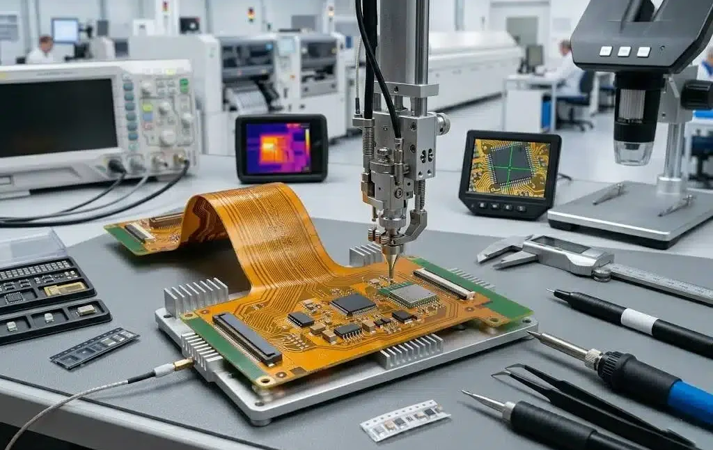
A flex tail is designed to bend, but only in the region and in the direction that the designer intended. The bend radius has to stay above the minimum, and the bend line has to run across the traces rather than along them.
The tail should be clamped at both ends of the bend so that the bend happens in the middle of the free length. A tail that is allowed to bend at the connector concentrates all the strain at the transition, and the coverlay edge is where the copper fractures first.
A stiffener behind a connector or a component on the flex is a strain relief feature, since it stops the flex from bending at the most vulnerable point. The stiffener is bonded to the flex and its edge becomes the new bend line, so it has to be placed where a bend is acceptable.
Where a flex is used as a hinge, the material and the copper type have to be selected for the cycle count as well as for the electrical function. The flex materials comparison covers the choice.
Vibration and Fatigue
A load that is small and constant is survivable, while a load that is small and repeated is not. Vibration applies millions of cycles, and a joint that is stressed even slightly will fail by fatigue rather than by overload.
The fatigue life depends on the stress amplitude, and the amplitude at a joint is set by the mass that the joint carries and by the length of the lever. A heavy connector at the end of a long board is a fatigue problem waiting for a vibration test.
The usual measures are to add support close to the heavy part, to lower the centre of mass of the assembly, and to avoid mounting the board in a way that lets it flex. A board that is held at two corners can flap, while one that is supported at four edges cannot.
Where a component or a connector has to be large, a mechanical support such as a bracket or a board to board spacer is the answer. The board quality check after the vibration test should include the joints around any heavy part.

Design and Verification
The design review should ask, for every cable, connector and flex tail, which feature carries the mechanical load. If the answer is the solder joint, a strain relief feature is missing.
The verification is a pull test on a sample for a cable, a bend cycle test for a tail, and a vibration test for the assembly. The pull test is quick and it finds the joint that would otherwise fail in the field.
The board outline and the panel design also matter, because a board that is broken out of a panel with a rough tab can carry a crack into the laminate that later becomes a strain concentration. The tab design is part of the mechanical quality of the finished board.
Finally, the assembly instructions should state where the strain relief is applied and what it is made of. A process step that is left out in production is the same as a feature that was never designed.
FAQ
Does every cable need strain relief? Every cable that can be pulled, moved or vibrated does. A cable that is potted in place or that never leaves the factory may not need a separate feature.
Is a hot melt adhesive a good strain relief? A soft, high elongation adhesive is, provided the surface is clean. A rigid one transmits the load instead of absorbing it and can make the joint more likely to crack.
Why does a flex tail break at the connector? Because the bend is concentrated at the transition where the stiffener or the coverlay ends. Clamping both ends moves the bend into the free length of the tail.