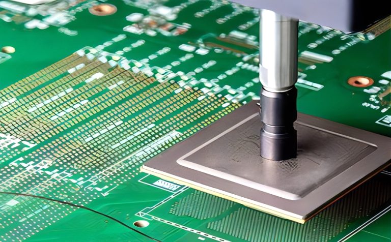
Tdr Impedance Measurement: Design Rules and Process Limits
A TDR impedance measurement sends a fast edge down a trace and watches the reflection that comes back. The reflection is a picture of the impedance along the line, so the instrument shows the trace, the via, the connector and the pad as a single curve. It is the most direct way to check that a controlled impedance board was built as designed, and it is also the measurement that is most often misread.
What TDR Measures
A time domain reflectometer launches a step or an impulse into the line and measures the voltage that returns. A reflection appears wherever the impedance changes, and the sign and the size of the reflection give the direction and the magnitude of the change.
The instrument converts the time axis into a distance using the propagation velocity of the line. The result is an impedance profile against distance, which is exactly the information the designer wants.
The measurement is one ported, so it sees the line from one end. A line that is terminated at the far end with a matched load shows only the imperfections in between.
The technique is used on a coupon, on a finished board and on a cable, and the interpretation is the same in all three cases.
Rise Time and Resolution
The rise time of the edge sets the resolution of the measurement. A fast edge resolves small features, while a slow edge averages them into a smooth curve.
The spatial resolution is roughly half the product of the rise time and the propagation velocity, which for a fast instrument is a fraction of a millimetre. A feature that is shorter than that cannot be seen separately.
The same property limits the accuracy of an impedance reading on a short line. If the line is shorter than the resolution, the instrument reads an average of the line and the transitions rather than the line impedance.
A slow edge is sometimes used deliberately, because it averages the roughness of the profile and gives a value that is closer to what the signal sees. The choice of rise time is therefore part of the measurement method, not a fixed instrument setting.

Launch and Probing
The launch is where the measurement starts, and it is the largest source of error. A probe that touches the trace with a long ground lead adds an inductance, and the inductance appears as a spike in the first part of the curve.
A proper launch uses a ground signal ground arrangement with the shortest possible ground path, or a coaxial launch soldered to the coupon. The difference between the two methods on the same line can be several ohms.
The probe also loads the line with its capacitance, which slows the edge and shifts the apparent impedance at the launch. The effect is largest on a narrow line and smallest on a wide one.
The test coupon design should include a launch pattern that matches the probe, because a coupon that cannot be measured is a coupon that proves nothing.
Reference Plane and Calibration
The reference plane is the point at which the measurement starts, and it is defined by the calibration. A calibration at the instrument port puts the reference plane far from the board, so the cable and the probe become part of the measured line.
A calibration at the probe tip removes the cable and the probe from the result, and it is the only way to measure a short trace accurately. The standard open, short and load calibration is used with a small kit that matches the probe.
The calibration has to be repeated when the probe, the cable or the setup changes, and it should be verified on a known standard before the board is measured. A drifting calibration is the most common reason for a measurement that disagrees with the design.
The reference impedance of the instrument is normally fifty ohms, and the result is quoted against it. A line that is designed for a different impedance is read directly, but the calibration standard still has to be fifty ohms.
Reading the Result
The curve shows the trace as a flat region, and any deviation is a discontinuity. A step up in impedance is an inductance or a narrow section, and a step down is a capacitance or a wide section.
A via appears as a dip followed by a peak, because the via pad is capacitive and the barrel is inductive. A connector appears as a longer disturbance that depends on its internal geometry.
The impedance of the trace itself is usually read from the flat region in the middle, away from the launch and the far end. Reading the value at the beginning is a common mistake, because that region contains the launch inductance.
The measured value should be compared with the design target and with the tolerance that the interface allows. A trace that is a few per cent off is usually acceptable, and the high speed design rules give the context for the tolerance.
Coupons and Panels
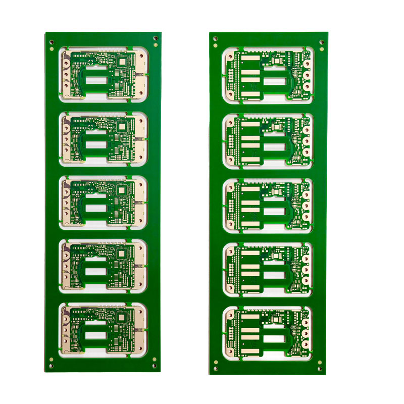
A coupon is the practical way to check a production panel, because it can be measured without disturbing the product and it can be probed at a launch designed for the purpose.
The coupon should carry the same trace width, the same stackup and the same material as the product, and it should be positioned so that it sees the same plating and etching conditions. A coupon from the edge of the panel and a trace from the middle are not the same line.
The coupon is usually measured on a sample basis, and the result is recorded as part of the panel documentation. A trend of drifting impedance across a batch is a process signal rather than a single board problem.
Where the board itself must be measured, a flying probe cannot do it, because the technique needs a fast launch. A finished board measurement is done with a probe station and a coupon-like launch.
Practical Rules
Calibrate at the probe tip, and verify the calibration on a standard before the board is measured. Most disagreements with the design come from the setup rather than from the board.
Use the shortest possible ground path on the probe, and treat any spike at the start of the curve as an artefact of the launch rather than a property of the trace.
Read the impedance from the flat middle of the line, and check the length of the line against the resolution of the setup before trusting the value.
Record the result with the coupon, the probe and the rise time, so that the next measurement can be compared with it. The quality record is only useful if the method is the same.
FAQ
Why does my TDR reading disagree with the design? Usually because the calibration reference plane is not at the probe tip, or because the launch adds inductance. Both are setup issues rather than board issues.
What rise time should be used? Fast enough to resolve the features of interest, and slow enough that the result is repeatable. The interface specification often names the rise time to use.
Can a TDR measure a finished board? It can, with a probe launch and a good calibration, but a coupon designed for the measurement gives a better and more repeatable result.