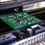
Placement Nozzle Types and Selection for SMT Lines
A placement nozzle is the only part of a pick and place machine that touches the component, and it is usually the cheapest item in the chain. That combination explains why it is so often the cause of a problem that is chased through the vision system, the feeder and the program instead. Choosing a placement nozzle is a matter of matching the tip to the part, the vacuum to the mass, and the material to the wear the line will impose.
What a Nozzle Has to Do
The nozzle has to pick a component from a feeder or a tray, hold it against acceleration and vibration, place it on a pad without moving it, and release it cleanly. Each of those four duties puts a different demand on the design, and a tip that is excellent at one can be poor at another.
The hold is usually the limiting duty. A part held by vacuum is supported only over the contact area, so a heavy component needs a larger tip, a higher vacuum or a lower acceleration, and those three options trade against speed and against the risk of marking the part. The contact area also decides whether the tip can reach a part in a tape pocket at all, since a tip wider than the pocket presses on the carrier tape instead of on the component.
Vacuum Nozzles Versus Mechanical Grippers
Most surface mount placement uses a vacuum nozzle, because it is simple, fast and self centring to a degree: the tip only has to reach a flat surface, and the part settles as the vacuum draws it down. Mechanical grippers appear where a part has no flat top surface to offer.
Grippers add complexity, because two jaws have to close to a controlled width and the closing force can damage a fragile body. They are used for connectors, shields and unusual packages, and they are almost always the slower option that needs its own setup and its own program step.

Matching the Tip to the Component
The tip diameter is chosen from the component size and the flat area available on the body. A tip that is too small for the part produces a weak hold and a placement offset that grows with speed, while a tip that is too large can overhang a small body and touch the neighbouring pads.
The shape matters as well as the diameter. Chip components are handled with a flat tip, a ball grid array or a land grid array needs a tip that does not touch the balls, and a part with a central recess needs a tip that reaches the flat rim rather than the cavity.
Nozzle Materials and Wear
Tips are made from ceramic, tungsten carbide, stainless steel and plastics, and the choice is a trade between wear life and the risk of marking. Ceramic resists abrasion and is normally the reference choice for a high volume line, while a plastic tip is used where the component surface cannot tolerate a hard contact. Hardness also interacts with the finish on the part: a hard tip on a soft tin plated surface leaves a witness mark that survives reflow, and that mark is a defect on some customer drawings.
Wear shows up gradually. A tip that has been eroded at the rim loses vacuum, and the result is a slow increase in placement errors that no program change will fix. Nozzles should be inspected at a defined interval and replaced on a schedule rather than when a defect finally appears.
Airflow, Vacuum and Sensing
The machine measures the vacuum at the tip, and that reading is how it knows whether a part was picked. A tip that is partly blocked or worn will still place a part, but the reading drifts until the sensor logic begins to reject good picks and the operator starts overriding it.
Vacuum level and airflow rate are separate settings. A high flow rate with a low vacuum can lift a light part too quickly, while a high vacuum with a small bore holds a heavy part firmly but releases slowly. Both should be set against the smallest and the largest part on the same head.
<img src="https://www.gopcba.com/wp-content/uploads/2026/08/word-image-24809-3.png" alt="Placement head picking a chip component with a vacuum nozzle tip” />
Special Cases: Connectors, Odd Forms and Dies
Connectors and odd form parts are usually placed on a separate machine with a custom tip or a gripper, because their mass and their shape fall outside the range that the high speed head handles well. A dedicated tip that holds the body rather than the top surface is often the practical answer.
Bare dies and thin substrates bring the opposite problem. The surface cannot be touched by a hard tip and the part cannot be deflected at all, so a soft tip with a controlled contact area is used and the placement force is reduced to the minimum the machine allows. The placement tolerance on these parts is often a fraction of the pad width, so the machine runs at reduced speed and the tip is replaced more often than the schedule would otherwise require.
Nozzle Storage, Cleaning and Inventory
Tips are easily damaged and easily mixed up. A tray with numbered positions, a record of the tip fitted to each head position and a cleaning routine for the bore keep the line predictable, and the record is what allows a placement problem to be traced to one specific tip.
Cleaning is often neglected, because the bore cannot be seen. Flux and dust drawn into the tip reduce the effective opening, and a tip cleaned with a solvent that attacks its seal will leak for the rest of its life.
Placement Problems Traced to the Nozzle
A component placed slightly off centre, a part that stands up during reflow, or a placement that is correct at slow speed and wrong at full speed all point at the pick rather than at the board. The nozzle tip diameter, the vacuum setting and the tip condition are the first three items to check.
Missing parts after placement usually come from a nozzle that dropped the component during travel, which is a vacuum or an acceleration issue, while a mark on the top of a part is a tip material issue. Systematic checks of these patterns appear in the wider catalogue of solder defects and board failures. An offset that survives those checks normally shows up at inspection as a shift in the same direction on every board, and the way that data separates a nozzle fault from a support fault is described in the guide to automated optical inspection.
Selection Checklist and Qualification
A selection checklist should list the component range, the flat area available on each body, the tip diameter chosen for each one, the material, the vacuum setting and the expected replacement interval. It belongs with the machine documentation and should be reviewed whenever a new product is introduced.
Qualification is a short placement trial rather than a formal study. Running the new tip for a few hundred placements across the component range and comparing the resulting offsets shows whether the tip holds the part consistently, and those offsets should sit inside the tolerance the design allows.
FAQ
How often should nozzles be replaced? On a schedule rather than on failure, with the interval set from the observed wear rate in the machine. A tip that is measured and replaced after a fixed number of placements is far less disruptive than one that fails in the middle of a build.
Can one tip handle a whole product? Often it can, if the components are similar in size and have a comparable flat area. Where the range is wide, two or three tips are usually better than a compromise diameter that is slightly wrong for everything.
Does a bigger nozzle hold better? It holds a heavier part, but it also touches more of the surface and can interfere with neighbouring features. The correct diameter is the smallest one that gives a reliable pick and a stable placement at the required speed.