
PCB Antenna Design and the Effect of the Ground Plane
A PCB antenna is a tuned structure that happens to be made of copper on a board, and its performance depends on everything around it. The ground plane, the enclosure, the battery, the hand of the user and the components placed nearby all change the resonance and the radiation. This article explains how the antenna and the ground plane work together, what the keep out rules are protecting, and how to lay out a board so that the antenna performs as the module vendor measured.
How a PCB Antenna Works
A printed antenna is a conductor shaped so that it resonates at the intended frequency and radiates the energy delivered to it. Its electrical length is set by the physical dimensions and by the dielectric constant of the material around it, and any change to either shifts the resonance.
At the frequencies used by most wireless products the wavelength is comparable to the board size, so the board itself becomes part of the radiator. That is the point most often missed in layout: the antenna is not an isolated component, and treating it as one produces a design that measures well on the bench and poorly in the product. The layout of the copper around the antenna is therefore as important as the antenna geometry itself.
The Ground Plane as Part of the Antenna
For a small antenna the ground plane acts as the other half of the radiator. Its size and shape set the bandwidth and the radiation pattern, and a ground plane that is too small makes the antenna difficult to match and sensitive to everything near it.
The ground plane also carries the return current for the feed. The path that current takes from the feed point back to the source is part of the radiating system, and an interrupted or a narrow return path changes the antenna behaviour directly. A slot in the ground plane under the feed is enough to change the match noticeably.
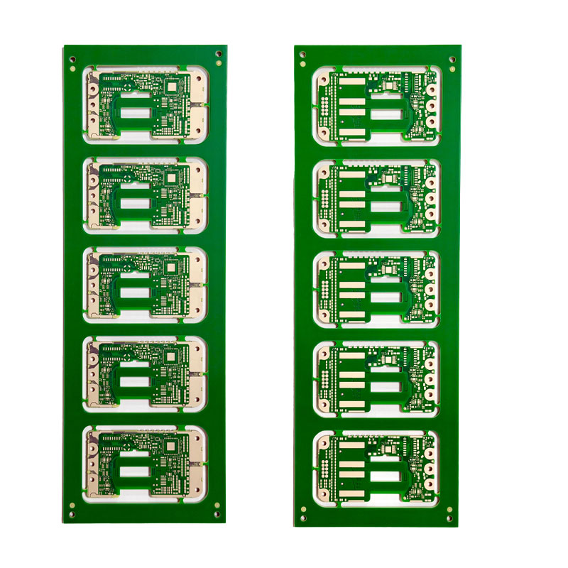
Keep Out and Clearance Rules
The keep out area is the region around the antenna where no copper, no component and no ground plane is allowed. It exists because any conductor in that region couples to the antenna, changes its resonance and absorbs radiated energy.
The keep out applies on every layer, not only on the layer the antenna is printed on. A ground plane on the layer below the antenna is as damaging as one beside it, and this is one of the most common layout errors. The keep out should be drawn as a rule in the layout tool so that a later edit cannot quietly fill it in. Our EMI immunity notes describe how the same layout decisions affect the immunity side of the design.
Antenna Types and Their Footprints
A chip antenna is a small ceramic component that is placed on the board and uses the ground plane beneath it. It needs a defined clearance area and a specific placement relative to the ground plane edge. A PCB trace antenna is printed directly on the board, which saves cost, and it needs a larger area and a well defined ground plane edge.
A wire antenna or a connector for an external antenna avoids the layout constraints altogether. The trade is the cost, the assembly step and the mechanical space, and for a product that has room for it, an external antenna is often the least risky choice. The decision should be made early, because an external antenna changes the mechanical design and the connector placement.
Feeding and Impedance Matching
The feed line has to deliver power to the antenna with a controlled impedance and without radiating itself. A microstrip feed of the correct width over the correct dielectric does that, and a long or badly routed feed line becomes a radiator that interferes with other parts of the product.
Matching is normally done with a pi network of components next to the antenna, so that the impedance can be adjusted after the board is built. The component footprints should be included even if they are initially unpopulated, because adding them later requires a new board revision. The footprints also give the tuning step somewhere to work when the first samples are measured. Our high frequency laminate guide covers how the dielectric properties affect the match.
Effect of the Enclosure and the Battery
Plastic changes the effective dielectric constant around the antenna and shifts the resonance, while metal reflects and absorbs. A metal enclosure or a metal coated plastic part near the antenna will detune it and reduce the radiated power, often by more than the antenna gain margin can absorb.
The battery is the other large conductive object in most portable products, and its position relative to the antenna matters as much as the enclosure. Both should be present in the physical sample that is used for the measurement, because a measurement on a bare board does not represent the product. An antenna that is well matched on a bare board can be badly detuned once the product is assembled.
Measuring Performance
Return loss and VSWR measured with a network analyser show whether the antenna is matched at the intended frequency, and they are the fastest check during development. Radiation pattern and efficiency require a chamber, and they answer the question that return loss cannot: how much of the power actually leaves the product. Both measurements are needed, because a good match with a poor pattern is a common outcome.
The measurement should be made with the product in its enclosure and in the orientations that matter, including the presence of a hand or a body where that is realistic. Our ferrite bead notes describe how unwanted coupling on the feed and the supply lines can be reduced once the layout is fixed.
Layout Mistakes That Detune the Antenna
The common mistakes are a ground plane that extends into the keep out, a copper pour or a trace routed close to the antenna, a component placed in the clearance area, a feed line that is not impedance controlled and a keep out that exists on the top layer only.

A second group of mistakes relates to the mechanical integration: a metal screw or a shielded can placed in the radiation path, a battery positioned directly under the antenna, or a cable routed across the keep out. These are not layout errors in the traditional sense, but they have the same effect. Reviewing the mechanical assembly against the keep out is a cheap check that catches most of them before the boards are built.
Working With the Module Vendor
Module vendors publish placement rules and keep out dimensions that were measured with their own board. Those rules should be treated as the minimum, and the design should be measured again in the actual product before release.
At gopcb the antenna area is checked at the data review stage along with the rest of the layout, and the design release checklist asks for the keep out and the feed impedance to be stated before the board is built.
FAQ
How large should the ground plane be? It depends on the antenna and on the frequency, and the module vendor data is the starting point. As a rule, a larger ground plane improves the bandwidth and reduces the sensitivity to nearby objects.
Can the antenna be tuned after the boards are built? Yes, within the range of the matching network. The matching components can compensate for a modest shift, but they cannot recover the efficiency lost to a ground plane in the keep out.
Does a metal enclosure always block the antenna? It does unless an opening, a plastic window or a slot antenna is designed for the purpose. A metal enclosure with no deliberate aperture is a shield around the antenna.