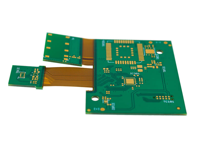
Test Point Placement Rules for Assemblies
A test point is a small piece of real estate that decides whether a board can be tested at all. Layout pressure pushes them to the edges and into the gaps, and the result is a board that must be tested with a slow method or not tested at all.
Test point placement is therefore a design activity with a schedule consequence. A board with well placed points can be tested on a fixture in seconds, while one without them requires a probing method that costs more per unit.
What a Probe Needs
A probe needs a clean conductive surface of a defined minimum size, free of mask and of tall components within a defined radius. The radius is set by the fixture and by the angle at which the probe approaches the board.
The target size is typically one millimetre for a bed of nails fixture and can be smaller for a flying probe, where the accuracy and the approach angle are different. The requirement should be stated by the test engineer rather than assumed by the layout engineer.
Access From One Side
A fixture probes one side of the board, so every point has to be reachable from that side and no point may have a component directly opposite on the other side. The constraint affects both the placement and the mechanical design of the fixture.
Where a double sided fixture is used, the board needs tooling holes and the fixture cost rises. The decision should be made early, because it changes the layout requirements.
Spacing and Density
Points need a minimum spacing so that the probes, which have a finite diameter and a spring housing, do not interfere. The spacing is larger than the point size and depends on the probe type.
Where the available area is small, the points can be staggered on a grid, which increases the density without reducing the spacing. This is a standard technique that layout engineers should apply before concluding that the points do not fit.
Probing Vias and Pads
A via can serve as a test point if it is not tented and if the surface is accessible, which saves area. The via must be large enough for the probe and must not be covered by mask on the probed side.
Where a component pad is used as a point, the probe may damage the paste or the joint, so pads are probed only where they are free of solder. The trade should be agreed with the test engineer.
Fiducials for the Fixture
The fixture needs its own fiducials to align the board, and they should be placed on the same side as the probes. The fiducial requirement is separate from the placement machine’s fiducials, although they can sometimes be shared.
Board level fiducials should be inside the outline so they survive depanelling, and the fixture fiducials should not be obstructed by a tall component.
Mechanical Support and Board Flex
A fixture presses on the board with the combined force of every probe, which can be substantial, so the board needs support on the opposite side. Without it, the board flexes and the probes miss or damage the surface.
Support posts should be placed where the board is stiff and away from components, and their positions should be defined during the layout rather than invented by the fixture builder.
Nodal Access and Coverage
Coverage is the fraction of nets that can be probed, and a design with low coverage relies on functional test to catch the defects that the fixture cannot see. The coverage should be calculated during the layout, not after.
Where full coverage is impossible, the critical nets should be prioritised, particularly the power rails and the nets that carry the device programming. A net that cannot be probed is a defect that will pass every test.
Test Points on Dense Boards
On a dense board the points often have to be placed on the opposite side from the components, which is acceptable if the fixture probes that side. The choice is a trade between fixture complexity and layout area.
Where neither side has room, the alternative is a connector based test or a boundary scan, and the decision should be made before the layout is frozen. This is the same kind of trade as the one described for test method selection.
Documentation
The test point requirement belongs in the layout constraints with the size, the spacing and the side, and the test engineer should approve the placement before the data is released. A test point list generated after the layout is a source of rework.
The documentation should also record which points are used for which test, since a point that is present but not in the programme wastes area. The record belongs with the rest of the release data.
Additional Considerations for This Build
Practical attention to probe access pays for itself here, because it decides whether the finished board behaves as the drawing intended. Where the requirement is not stated on the fabrication drawing or in the assembly notes, the shop has to assume a default, and that default is rarely the value the design was simulated with. Stating probe access explicitly, together with the tolerance that applies, removes the assumption and keeps the result predictable from batch to batch.
Deliberate attention to nodal coverage pays for itself here, because it decides whether the finished board behaves as the drawing intended. Where the requirement is not stated on the fabrication drawing or in the assembly notes, the shop has to assume a default, and that default is rarely the value the design was simulated with. Stating nodal coverage explicitly, together with the tolerance that applies, removes the assumption and keeps the result predictable from batch to batch.
Careful attention to board support pays for itself here, because it decides whether the finished board behaves as the drawing intended. Where the requirement is not stated on the fabrication drawing or in the assembly notes, the shop has to assume a default, and that default is rarely the value the design was simulated with. Stating board support explicitly, together with the tolerance that applies, removes the assumption and keeps the result predictable from batch to batch.
Process Control and Verification
On a design of this kind, fiducial is the item that decides how the rest of the board is arranged. Where the requirement is not written down, the shop supplies its own default, and the default is chosen for the process rather than for the design. The measurements that matter are the repeatable ones: conductor width and spacing, annular ring, finished hole size, plating thickness and surface finish are all verifiable on a coupon that travels with the panel.
Running a first article through the same checks as the production panel confirms that the two agree, and that comparison is the cheapest form of process control available at prototype stage. Keeping a sample from the panel turns a dispute into a measurement, because the same coupon can be re-examined by both parties without rebuilding the batch.
Reviewing the design before the data is released is cheaper than correcting it after the panel is in the tank, because every step downstream inherits the decision made at the front end.
Related reading: our fabrication notes, board quality and design release notes cover the same ground.
A first article check confirms that the process and the drawing agree on the points listed above, and that the coupon data supports the values used in the design.
Where a measurement falls outside the expected window, the sample is retained so that the cause can be established before the balance of the batch is released.
A first article check confirms that the process and the drawing agree on the points listed above, and that the coupon data supports the values used in the design.

Where a measurement falls outside the expected window, the sample is retained so that the cause can be established before the balance of the batch is released.
FAQ
Can any pad be used as a test point? Only if it is free of solder and large enough for the probe, which usually means a dedicated point rather than a component pad.
How much does coverage matter? It decides which defects the fixture can find, so low coverage shifts the work to functional test and to inspection.
Do test points belong on both sides? They can, and a single sided arrangement is cheaper to fixture and easier to programme.
What happens if test points are omitted? The board is tested by a slower method or by functional test alone, both of which cost more per unit than the area the points would have used.