EMI Gasket and Contact Design
A gasket is the part that closes the gap between a shield and a housing, and it works only if it is compressed and if the contact surfaces are conductive. The design is therefore about force and about surface, not about the gasket material alone.
A gasket that is not compressed enough leaves a slot, while one that is over compressed takes a permanent set and loses its spring. The window between the two is narrow.
How Shielding Depends on the Seam
The field escapes through the seams and the apertures rather than through the material, so the gasket has to make the seam electrically continuous. The spacing between contact points is what determines the frequency at which the seam begins to leak.
The contact spacing should be chosen from the highest frequency of interest, which is a calculation rather than a rule of thumb.
Compression and Deflection
The gasket is specified with a compression range, and the housing has to apply a force inside that range at every point along the seam. A housing that is not stiff enough deflects in the middle and leaves the centre uncompressed.
The force should be verified on a sample by measuring the gap after assembly. This is the same verification approach used for a thermal interface, where the gap is the controlling dimension.
Contact Resistance
The resistance across the joint depends on the plating, the force and the cleanliness of both surfaces. An oxidised or painted surface has a high resistance even when the gasket is correct.
The measurement is made with a four wire method across a sample joint, and the result should be compared with a limit. A high reading points to a surface problem rather than to the gasket.
Materials and Plating
Gaskets are made from conductive elastomer, fabric over foam or metal fingers, and each has a different compression behaviour and a different durability. The choice follows from the number of openings the product will see.
The plating on a metal gasket determines the corrosion behaviour against the housing material. A dissimilar pair can corrode in humidity, which raises the resistance over time.
Attaching the Gasket to the Board
Where the gasket contacts the board rather than the housing, the board needs a ground pad with vias to the plane, and the pad should be masked off from any coating. The pattern is described with shield grounding design.
A gasket that contacts a coated surface makes no reliable connection, so the coating keep out is part of the gasket design.
Assembly and Handling
A gasket should be installed so that it is not stretched, since a stretched gasket is thinner in the middle and may not recover. The installation method should be defined rather than left to the operator.
Where a gasket is adhesive backed, the surface should be cleaned before it is applied, for the same reason that a coating needs a clean surface.
Verification
Verification is by a contact resistance measurement on a sample and, where the requirement is critical, by an emissions test on a complete unit. The resistance measurement is the production check.
The measurement should be made at several points along the seam, since a single reading can miss a local gap.
Records
The records should include the gasket material, the lot, the compression gap and the resistance measurement. Where a unit fails an emissions test, those records show whether the gasket was the cause.
They belong with the assembly evidence described for manufacturing processes.
Additional Considerations for This Build
Practical attention to EMI gasket pays for itself here, because it decides whether the finished board behaves as the drawing intended. Where the requirement is not stated on the fabrication drawing or in the assembly notes, the shop has to assume a default, and that default is rarely the value the design was simulated with. Stating EMI gasket explicitly, together with the tolerance that applies, removes the assumption and keeps the result predictable from batch to batch.
Deliberate attention to seam continuity pays for itself here, because it decides whether the finished board behaves as the drawing intended. Where the requirement is not stated on the fabrication drawing or in the assembly notes, the shop has to assume a default, and that default is rarely the value the design was simulated with. Stating seam continuity explicitly, together with the tolerance that applies, removes the assumption and keeps the result predictable from batch to batch.
Process Control and Verification
On a design of this kind, EMI gasket is the item that decides how the rest of the board is arranged. A stack-up that is drawn rather than described removes most of the ambiguity from a quotation, and it lets the fabricator price the board against the dielectric and copper weights that will actually be used. Where the requirement is not written down, the shop supplies its own default, and the default is chosen for the process rather than for the design.
The measurements that matter are the repeatable ones: conductor width and spacing, annular ring, finished hole size, plating thickness and surface finish are all verifiable on a coupon that travels with the panel. Running a first article through the same checks as the production panel confirms that the two agree, and that comparison is the cheapest form of process control available at prototype stage.
Keeping a sample from the panel turns a dispute into a measurement, because the same coupon can be re-examined by both parties without rebuilding the batch. Reviewing the design before the data is released is cheaper than correcting it after the panel is in the tank, because every step downstream inherits the decision made at the front end.
Documenting the assumption is part of the design work, and a short note on the drawing prevents a question that would otherwise arrive a day later and cost a day of schedule. The process window is set by the narrowest step in the flow, so an improvement anywhere else shows up as margin rather than as yield until that step is addressed.
Process Control and Verification
On a design of this kind, EMI gasket is the item that decides how the rest of the board is arranged. A stack-up that is drawn rather than described removes most of the ambiguity from a quotation, and it lets the fabricator price the board against the dielectric and copper weights that will actually be used. Where the requirement is not written down, the shop supplies its own default, and the default is chosen for the process rather than for the design.
Process Control and Verification
On a design of this kind, EMI gasket is the item that decides how the rest of the board is arranged. A stack-up that is drawn rather than described removes most of the ambiguity from a quotation, and it lets the fabricator price the board against the dielectric and copper weights that will actually be used. Where the requirement is not written down, the shop supplies its own default, and the default is chosen for the process rather than for the design.
A first article check confirms that the process and the drawing agree on the points listed above, and that the coupon data supports the values used in the design.
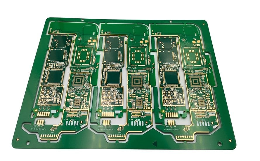
Where a measurement falls outside the expected window, the sample is retained so that the cause can be established before the balance of the batch is released.
A first article check confirms that the process and the drawing agree on the points listed above, and that the coupon data supports the values used in the design.
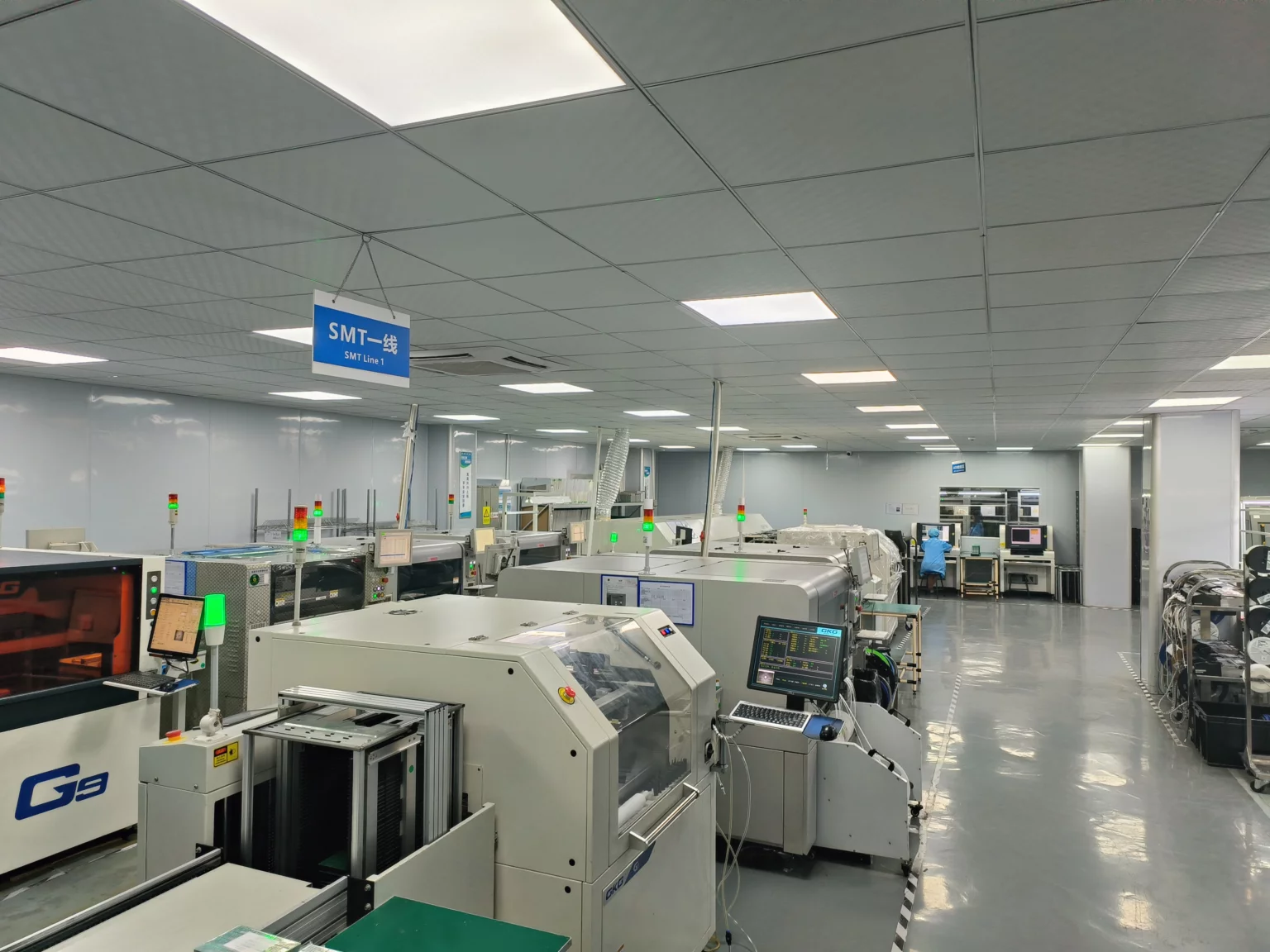
Where a measurement falls outside the expected window, the sample is retained so that the cause can be established before the balance of the batch is released.
FAQ
Does a gasket need to be glued in place? Where it is held by the housing it need not be, and a loose gasket can be displaced during assembly.
Why does resistance rise over time? Usually through corrosion at a dissimilar metal contact or through loss of compression.
Can a coated board carry a gasket? Only if the contact area is free of coating, since the coating is an insulator.
How is the seam checked? By a contact resistance measurement at several points after assembly.