Laminate Dielectric Constant Measurement Methods Guide
The dielectric constant of a laminate is the number that a signal integrity engineer uses to size every trace on a high speed board, so it is worth knowing exactly what a quoted value means. Suppliers quote it on a data sheet, test laboratories measure it with several different methods, and the numbers do not always agree, because the value depends on the frequency, the direction of the field and the way the sample was prepared. A quoted figure without a method and a frequency is of limited use, and the two should always be reported together.
Why the Value Matters
The dielectric constant sets the propagation delay of a trace and the impedance of a controlled line. A change of a few percent in the value moves the impedance out of tolerance, which changes the reflection at every discontinuity and can push a link outside its loss budget. The dielectric constant also controls the wavelength on the trace, so it affects every structure that depends on a quarter or a half wavelength.
It also determines the physical width of a trace for a given impedance. A material with a higher dielectric constant needs a narrower trace for the same impedance, which changes the manufacturable geometry and may push the design outside the etching capability of the shop. That interaction is why a material change should be evaluated by the fabricator and the designer together rather than by either alone.
What Dk and Df Mean
The dielectric constant, usually written as Dk, is the ratio of the permittivity of the material to the permittivity of free space. It describes how much the material slows a signal and how much energy is stored in the field around the trace.
The dissipation factor, written as Df, describes how much energy the material absorbs. The two are measured together because a low Df material is usually also a low Dk material, and because both change with frequency in ways that are not always intuitive. A material can be excellent at one frequency and only average at another, so the choice has to be made at the operating frequency.

Transmission Line Methods
A transmission line method measures a test structure that behaves like a real trace. A short line of known length is measured for delay and loss, and the dielectric constant is calculated from those results using the geometry of the line.
This family of methods is attractive because it measures the property in the form the designer actually uses. It also has a pitfall, because the calculation depends on the geometry, so any error in the measured trace width propagates directly into the answer. Cross sectioning the same coupon is a good way to confirm the geometry that the calculation assumed.
Resonator Methods
A resonator method measures a sample placed in a resonant cavity or formed into a resonant structure. The resonant frequency gives the dielectric constant and the width of the resonance gives the dissipation factor, and both are measured at a defined frequency.
The advantage is that the measurement does not depend on the trace geometry, which removes a large source of error. The disadvantage is that the sample has to be prepared precisely and that the measurement is made at a specific frequency rather than across a band. Where a design operates over a wide band, several measurements at different frequencies may be needed to describe the material adequately.
<img src="https://www.gopcba.com/wp-content/uploads/2026/08/pcb-assembly-company-pcbonline.jpg" alt="Test coupon used to verify dielectric constant on a PCB” />
Split Post Dielectric Resonator
The split post dielectric resonator is a common laboratory instrument in which a thin sample is placed between two halves of a cavity. It gives a repeatable measurement of both Dk and Df on a small sample at a defined frequency, and it is fast enough for routine material evaluation.
The sample thickness and flatness matter, because the field distribution changes if the sample does not fill the gap as expected. Air gaps between the sample and the cavity walls are the most common cause of an inconsistent result. Samples should be cut from a flat pressed panel rather than from a warped one, because the gap effect can be larger than the material difference being investigated.
Frequency Dependence
Dielectric constant falls as frequency rises for most laminate materials, and the dissipation factor rises. A value quoted at one gigahertz is therefore not the value that applies at ten gigahertz, and using the wrong figure is a common source of a design that does not perform. Interpolating between two published points is acceptable for an estimate, but the final design should be verified on the actual stack.
The shape of the curve also differs between material families. A PTFE based material is comparatively flat across a wide band, while some filled hydrocarbon materials change more quickly, which means the data sheets have to be compared at the frequency of interest. Our high frequency guide covers the practical consequences. Where a material is being considered for a new band, a measurement at that band is worth more than a data sheet curve extrapolated to it.
Sample Preparation
The sample has to represent the material in the form it will be used. A test on a bare laminate measures the dielectric, while a test on a finished board measures the dielectric plus the effects of the copper roughness, the resin rich layer at the foil interface and the mask on the surface.
That difference is why two laboratories can report different values for the same material. The report should state the method, the frequency, the sample form and the conditioning, because without those details the number cannot be compared with anything. The laboratory report should be retained with the design file so that a later comparison can be made on the same basis. Our laminate guide describes the properties that are normally specified. Conditioning matters as well, because absorbed moisture raises the dielectric constant measurably.
Comparing Supplier Data
Supplier data sheets are not always produced with the same method, so a direct comparison between two products can be misleading. The safest approach is to ask for the method and frequency, and to compare only values obtained the same way. Where two suppliers quote different methods, asking both for a measurement at the same frequency is a reasonable and inexpensive request.
Where the material is critical to the design, a measurement on the actual production stack is more reliable than the data sheet value. Our PTFE guide describes the properties of one family of low loss materials and how they are specified. A measurement on a coupon from the production stack settles the question of what the design will actually see.
Process Control Points
The controls are the material lot, the conditioning before measurement, the method and frequency, the sample preparation and the fixture calibration. A measurement reported without those details is not reproducible by anyone else. Recording the method and the frequency alongside the value is a discipline that costs nothing and prevents most disputes.
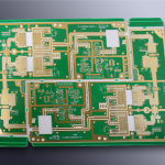
Production control is usually indirect. The dielectric constant is confirmed by measuring the impedance of a test coupon on the panel, which catches a thickness or a material error without a laboratory measurement. Our quality documentation describes how these results are recorded at gopcb.
FAQ
Why do two laboratories report different Dk values? They may use different methods, frequencies, sample forms or conditioning. A value is only comparable when those details match, so the report should state them.
Which method is best for a laminate? For material selection the split post resonator is convenient and repeatable. For design verification a transmission line structure on the production stack is more representative.
Does copper roughness affect the measurement? It does. Rough copper increases the apparent loss and slightly changes the effective dielectric constant, which is why a finished board measures differently from a bare laminate.