Polarity: Design Rules and Process Limits
A reversed component is one of the few defects that is both easy to prevent and expensive to find. A diode placed backwards, a capacitor inserted the wrong way round or an integrated circuit rotated by ninety degrees may damage itself on power up, may pass test and fail later, or may damage the surrounding circuit on the first switching event. Prevention is a documentation and verification problem rather than a technology problem.
Where Orientation Errors Come From
The causes are almost always in the information rather than in the assembly. An assembly drawing that shows a footprint without a marking reference, a footprint whose silkscreen does not match the part, or a reel whose marking convention differs from the library entry all invite a mistake. Operators place what they see, and the drawing is what they see.
The second cause is ambiguity in the part itself. Some packages have a marking on the underside, some have a chamfer that is hard to see, and some have a marking that is a date code rather than a polarity indicator. Each of those has to be resolved in the documentation before the part reaches the line.
Drawing and Marking Conventions
The assembly drawing should show the polarity marking of every polarised part unambiguously. The convention should match what the assembler sees on the real component and on the board, and it should be consistent across all drawings so that nobody has to remember which product uses which convention.
The silkscreen on the board is the reference the operator uses, so it has to be legible after assembly. A marking hidden under a component body, or one removed by a mask opening, provides no reference at all. Our article on silkscreen design rules covers the legibility requirements.
Machine Data and Library Entries
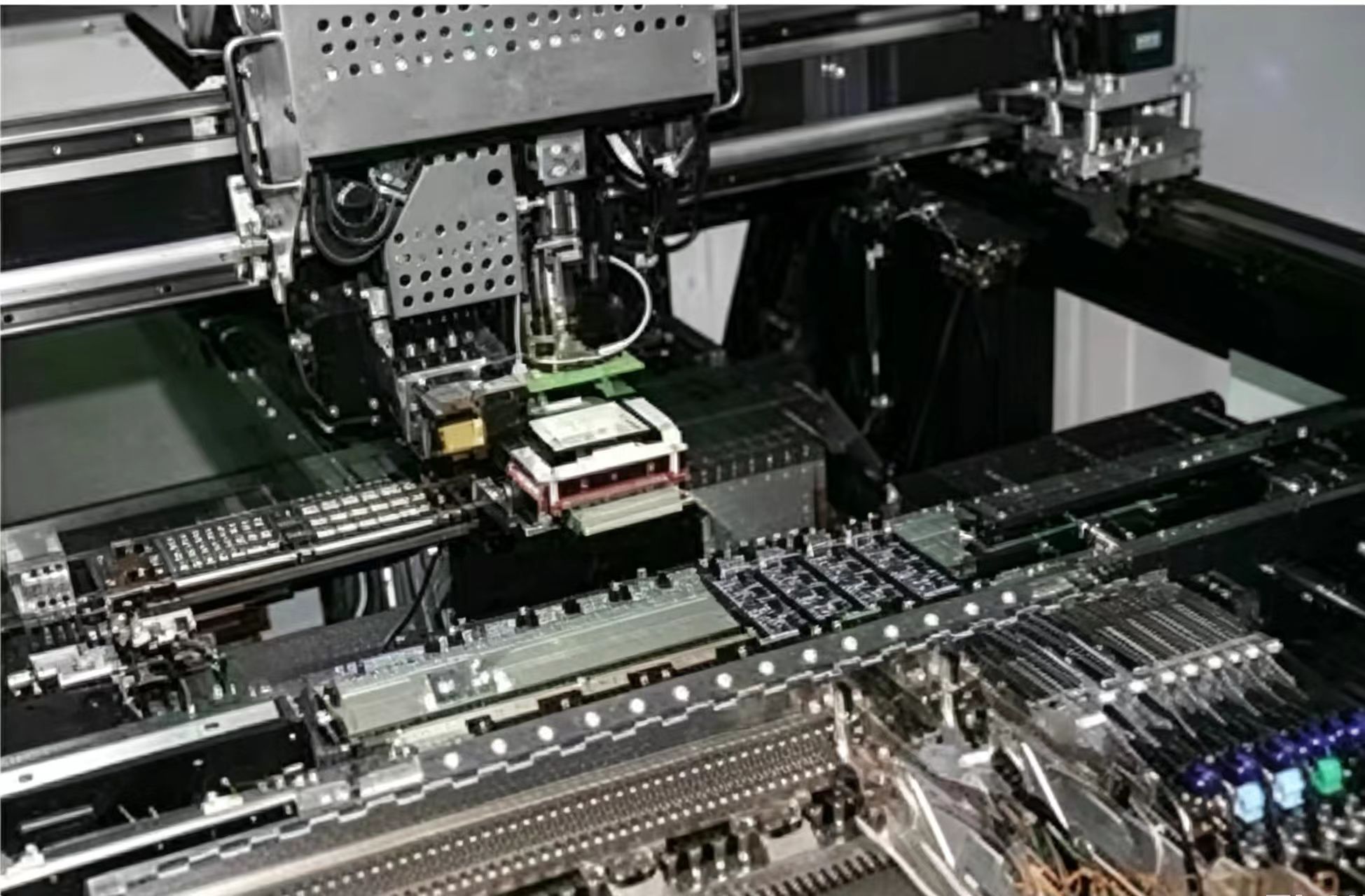
Automated placement moves the problem into the component library. A library entry with the rotation convention set incorrectly will place every instance of that part wrongly, and the error will be consistent, which makes it look correct on the board. Verification against a known good board is the only reliable check.
Reels add another dimension. The tape orientation determines how the part is presented, so a reel that is wound the other way presents the part rotated by a hundred and eighty degrees. The component record has to describe the presentation, not just the part, and the check belongs in the first article.
Visual Aids and Work Instructions
Work instructions work best when they show rather than describe. A photograph of the correctly oriented component in place, with the marking visible, removes the interpretation step. Where a part is difficult to orient, a marked sample board kept at the station is more effective than any written procedure.
The instructions should also say what to do when orientation cannot be determined. Stopping and asking is the correct behaviour, and it has to be explicitly permitted, because an operator who is measured on throughput will otherwise guess.

Verification Before and After Assembly
Verification starts at incoming inspection, where the marking convention of a new lot can be confirmed against the part number. It continues at setup, where the first article is checked against the drawing, and it ends with inspection, where optical systems check polarity on visible parts.
Optical inspection is effective for parts with a visible marking and useless for those with a marking on the underside or under a body. Knowing which categories a product contains tells you where manual checks are still needed, and the complementary methods are described in our article on automated optical inspection.
Design Choices That Reduce Risk
The design can remove the opportunity altogether in some cases. Choosing a footprint that shows the polarity clearly, keeping polarised parts out of areas that are difficult to inspect, and using asymmetric pad shapes that will not accept a reversed part are all effective.
Where two parts are electrically interchangeable but mechanically different, standardising on one orientation across the product removes a decision. Design for assembly is measured in decisions avoided, not only in seconds saved, and the same reasoning appears in our note on placement capability.
Investigation When an Error Occurs
Finding one reversed part should prompt a question about how many others exist. The batch boundaries are the material lot, the shift and the setup, and the first step is to establish which of those the affected unit belongs to. The same containment logic used for any defect applies.
The root cause is usually in the documentation or in the library rather than with the individual who made the mistake. Treating it as a training issue rather than a system issue guarantees that the same error returns with the next new part.
Process Control and Verification
Keeping a sample from the panel turns a dispute into a measurement, because the same coupon can be re-examined by both parties without rebuilding the batch. Reviewing the design before the data is released is cheaper than correcting it after the panel is in the tank, because every step downstream inherits the decision made at the front end.
Documenting the assumption is part of the design work, and a short note on the drawing prevents a question that would otherwise arrive a day later and cost a day of schedule.
Checks Before Release
The checks that matter are the ones performed on the product rather than on a sample kept for the purpose, because a coupon that travels with the panel is the only evidence about that panel. Where a requirement can be measured, it should be measured at the point of manufacture and recorded against the board or the lot it applies to.
A parameter that is set once and never re verified drifts, and the drift is usually discovered by a defect rather than by the record.
FAQ
Can AOI catch every reversed part? Only those whose polarity marking is visible from above. Parts with markings underneath, or hidden under a body, still require a manual check.
Should every polarised part have a silkscreen marking? Yes, and it should remain visible after assembly. A marking that is covered provides no reference and may as well not exist.
Why does the same part get reversed on one product only? Almost always because that product uses a different library entry or a different reel orientation. Comparing the two setups usually identifies the difference immediately.