Assembly Floor Layout and Flow
How a floor is laid out decides how far a board travels between operations, how much work in progress accumulates beside each station and how quickly a problem at one machine becomes a problem for the whole line. Layout is often treated as a facility decision made once and lived with for years, when in fact most of its consequences are engineering consequences: handling damage, queue time, WIP cost and the ability to see that a station is in trouble.
Flow Before Floor Space
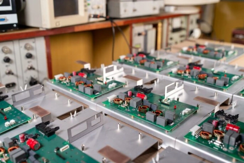
The starting point is the sequence of operations and the direction in which the product moves. A layout that follows the process order in a straight line or a U shape minimises travel and makes the flow visible. A layout that groups machines by type, with the board crossing the floor several times, is convenient for the equipment owner and expensive for the product, because every crossing is a handling opportunity and a queue waiting to happen.
Distance matters less than the number of transfers. Each time a board is picked up, placed in a different carrier and set down again, there is a chance of damage and a cost in time. Counting the transfers in the current route is usually more illuminating than measuring the metres, and the result is often a list of moves that could be eliminated by relocating one operation. Line balance work and layout work are closely related.
Work in Progress
Work in progress is the visible symptom of an unbalanced or unreliable process. It accumulates in front of the slowest station, in front of a machine that stops often and in front of any operation that is fed in batches. Some of it is unavoidable, particularly where processes have different cycle times or where an oven must run continuously, but the quantity should be defined rather than allowed to grow until the floor runs out of space.
The practical control is a limit per station, agreed with the people who work there, plus a clear rule about what happens when the limit is reached. A line that stops when the limit is hit surfaces the constraint immediately; a line that simply accumulates more stock hides it. The same principle is used in material staging, where a defined quantity at the point of use is easier to control than an open store.

Material Handling and Staging
Material should arrive at the station in the quantity needed, in a container that protects it and with the identification intact. Where that happens, the operator spends time building rather than searching, and the risk of a wrong part entering the build falls. Kitting, kanban replenishment and point-of-use storage are all mechanisms for achieving it, and the choice depends on the value and variety of the parts rather than on preference.
Handling equipment belongs to the layout decision. Trolleys, carts and conveyors should have a defined route and a defined parking position, so that they do not block an aisle or a fire exit when they are not in use. Board carriers and trays should be standardised so that a station does not need three different types, and their storage position should be marked on the floor. Changeover practice depends heavily on whether the material for the next job can be staged without disturbing the current one.
Bottleneck Placement and Visibility
The bottleneck station should be visible, accessible and supported. Placing it in a corner where it cannot be seen from the rest of the line guarantees that its problems are discovered late, and placing it where passing traffic interrupts the operator guarantees that it runs below its capability. Support functions, such as the repair bench and the supervisor’s position, should be located so that the constraint can be reached within seconds.
Visibility extends to the movement of the product. A layout in which the boards can be seen moving through the process tells everyone where the work is and how much is left, without a report. This is one of the arguments in favour of a single-piece or small-batch flow, and it is also why lines that are physically long often struggle to communicate status. Shift handover is much easier when the state of the line is visible from a single position.
Aisles, Access and Safety
Aisles have to be wide enough for the traffic that uses them, including the widest trolley and the maintenance access that a machine requires. A layout that fits on paper by making the aisles narrow will fail in practice, when a technician needs to open a panel or a trolley has to pass a stopped operator. Maintenance access is often forgotten until the first repair, and moving a machine afterwards is far more expensive than allowing for it initially.
Utilities constrain the layout as well. Compressed air, extraction, nitrogen and power all have to reach the machines, and their cost per metre varies enough to influence the arrangement. Where a machine needs extraction for fumes or dust, the duct routing should be planned with the same care as the product flow, because a long flexible duct with many bends reduces the extraction at the tool. Safety routes, emergency stops and fire equipment positions are non-negotiable constraints that should shape the layout from the start.
Improving an Existing Layout
Most engineers inherit a layout rather than design one, and the improvement path is incremental. The useful first step is a walk of the process with a stopwatch and a notebook, recording distance, transfers and waiting time at each step. That data usually identifies two or three moves that dominate the total, and those can often be addressed by relocating a bench, adding a roller conveyor section or changing the direction of a single operation.
Where a larger change is needed, a pilot on one product family gives evidence without committing the whole floor. Simulating the flow with cardboard or tape on the floor is an old technique that still works, because it makes the space real and exposes the conflicts that a drawing hides. The layout should be treated as a process parameter with a revision rather than as a fixed asset, and reviewed whenever the product mix changes substantially.
Additional Considerations for This Build
Practical attention to floor layout pays for itself here, because it decides whether the finished board behaves as the drawing intended. Where the requirement is not stated on the fabrication drawing or in the assembly notes, the shop has to assume a default, and that default is rarely the value the design was simulated with. Stating floor layout explicitly, together with the tolerance that applies, removes the assumption and keeps the result predictable from batch to batch.
Process Control and Verification
On a design of this kind, floor layout is the item that decides how the rest of the board is arranged. Reviewing the design before the data is released is cheaper than correcting it after the panel is in the tank, because every step downstream inherits the decision made at the front end. Documenting the assumption is part of the design work, and a short note on the drawing prevents a question that would otherwise arrive a day later and cost a day of schedule.
FAQ
What is the best basic layout shape? One that follows the process sequence, usually a line or a U. The shape matters less than eliminating backtracking and unnecessary transfers.
How much work in progress is acceptable? Whatever the constraint requires plus a small buffer. It should be defined per station and visible rather than allowed to accumulate.
Should material be kitted or pulled? Kit high-value or easily confused parts; pull commodities from a point-of-use location. Both reduce the time an operator spends searching.
How often should a layout be reviewed? Whenever the product mix or volume changes significantly, and after any change that shifts the bottleneck.