Component Polarity and Orientation Control
A component placed in the wrong orientation is usually functional at test and defective in the field. A reversed diode, an inverted electrolytic capacitor or a rotated connector can pass a quick test, survive the burn in and fail when the product is used. Polarity control is therefore a documentation, program and inspection problem rather than a soldering problem, and it is one of the few defects that can be eliminated almost completely.
How Orientation Errors Happen
The error is introduced at the design stage, at the programming stage or at the machine. A library symbol with the wrong pin numbering produces a program that places every part of that type incorrectly, which is the most damaging form because it is systematic. A program with a single wrong orientation produces one defect on every board.
The machine can also introduce errors through a feeder that is loaded with the tape the wrong way up, a reel that is spliced in the wrong orientation or a tray that is loaded incorrectly. These produce a defect that appears with a specific reel and disappears when it is exhausted, which is why the reel identity has to be recorded.
Marking and the Reference Designator
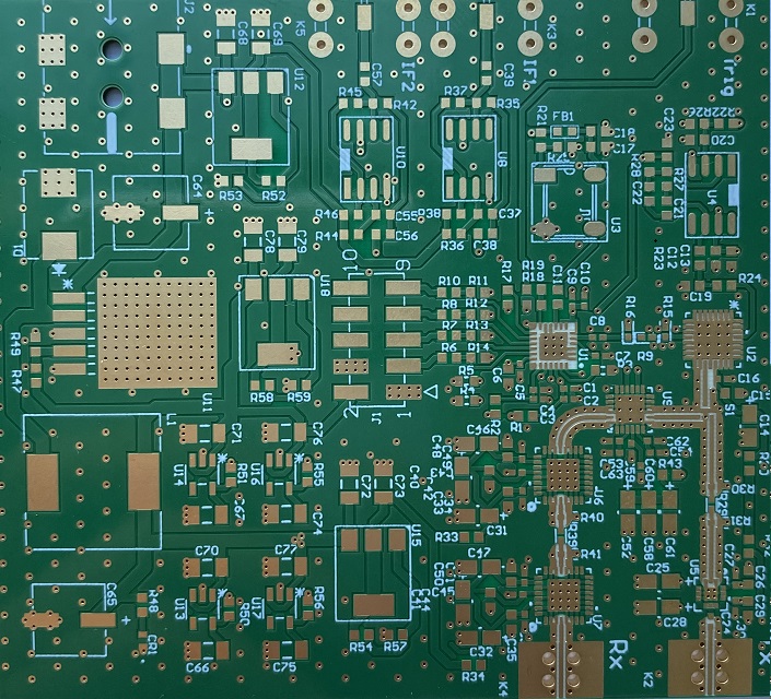
The board has to show the intended orientation. A silkscreen polarity mark, a pin one indicator or a chamfered outline gives the assembler and the inspector a reference, and its absence turns every check into an interpretation. Where the board is too dense for silkscreen, the mark can be placed on the mask or in the copper, but it must be present.
The mark should be unambiguous and should not be confused with other features. A polarity mark that is the same shape as a fiducial, or one that is placed under a component, provides no information. The conventions for placing such marks are part of the layout rules described alongside PCB quality assessment.

Program and Data Verification
The placement program is generated from design data, and the verification should be done on that data rather than on the machine. A review that compares the library orientation of each component with the drawing and with the marking on the board catches the systematic errors before a board is built.
Where a program is transferred or copied from a similar product, the verification has to be repeated, because the copy inherits assumptions that may no longer apply. The verification should be recorded with the program so that a later change can be traced, and the record should state which components were checked and against which reference.
Machine Setup and Feeder Verification
The machine verifies the feeder identity against the program and, on some systems, the orientation of the tape. Where the system supports it, the verification should be enabled rather than bypassed, because it catches the reel that was loaded incorrectly. The verification depends on the packaging data being correct, which is why the packaging information is part of the component record.
Offline setup of the feeders, described in feeder setup and changeover, supports this by moving the loading step away from the machine and giving it a defined procedure. A feeder prepared and verified offline is far less likely to be loaded incorrectly than one assembled at the machine under time pressure.
First Article Inspection
The first article is the point at which the whole chain is verified on a real board. It should confirm the orientation of every polarised component, not a sample, because the systematic error affects all of them equally. The check should be done against the drawing and the marking, and it should include the components that are difficult to see, such as those under a shield or beside a tall neighbour.
The first article should be repeated after a change of feeder, a change of reel, a program change or a machine change, because each of those can introduce the error independently. The documentation of the first article should record what was checked and the result, so that the verification is evidence rather than a statement.
Inspection Limits
Automated optical inspection can verify orientation for many package types, and it is effective where the polarity mark is visible and has good contrast. It is weak where the marking is on the underside of the component, where a laser mark has a low contrast or where the package is symmetrical in appearance and differs only in internal construction.
For those cases, electrical test is the only reliable check. A diode can be tested for forward voltage, a capacitor for polarity sensitive leakage and a connector for pin continuity. Where a component cannot be verified optically, the test coverage should be reviewed to confirm that a reversed part would be detected, and the reasoning behind that decision recorded.
Errors that escape both inspection and test are the expensive ones, and they are the reason the design and program verification matters more than the inspection.
Process Controls and Records
The controls are a correct library, a documented program verification, feeder identity checking where available, a recorded first article that covers every polarised part and a test coverage that would detect the failures that inspection cannot see. Each of those is cheap compared with the cost of a field failure.
The gopcb assembly group treats a polarity escape as a process incident rather than an isolated mistake, and the investigation always includes the library and the program as well as the operator action. That is because the systematic errors produce a whole batch of defective boards, and the only way to prevent the next batch is to correct the data rather than the person.
Checks Before Release
Documentation exists so that a person who was not present can reproduce the work and reach the same conclusion. The acceptance criteria should be written before the work starts, so that the decision is made by the specification rather than by the person inspecting.
Related reading: our fabrication notes, board quality and design release notes cover the same ground.
FAQ
Is AOI enough for polarity control? For packages with a visible mark, often yes. For parts where the marking is hidden or has low contrast, electrical test or a manual check is required.
How often should the first article be repeated? After any change to the program, the feeder setup, the reel or the machine. Each of those can introduce the error independently.
Why is a reversed component not always caught by test? Because many circuits tolerate a reversed part at low current or at room temperature, and the failure appears only at operating conditions.