
Plating Rack Maintenance: 5 Checks Before a Run
A plating rack is the electrical and mechanical interface between the rectifier and the panel, and most plating defects that are blamed on chemistry start here instead. The rack carries current to every panel through contact tips, holds the work at a fixed spacing, and has to survive immersion in hot acid without contaminating the bath.
Rack maintenance is therefore a process control, not housekeeping. Contact resistance, coating damage and the pattern in which panels are hung all change the current density the copper sees, and the result appears as thin plating in a hole, a burnt edge or a deposit that is heavy on one side of the panel and light on the other.
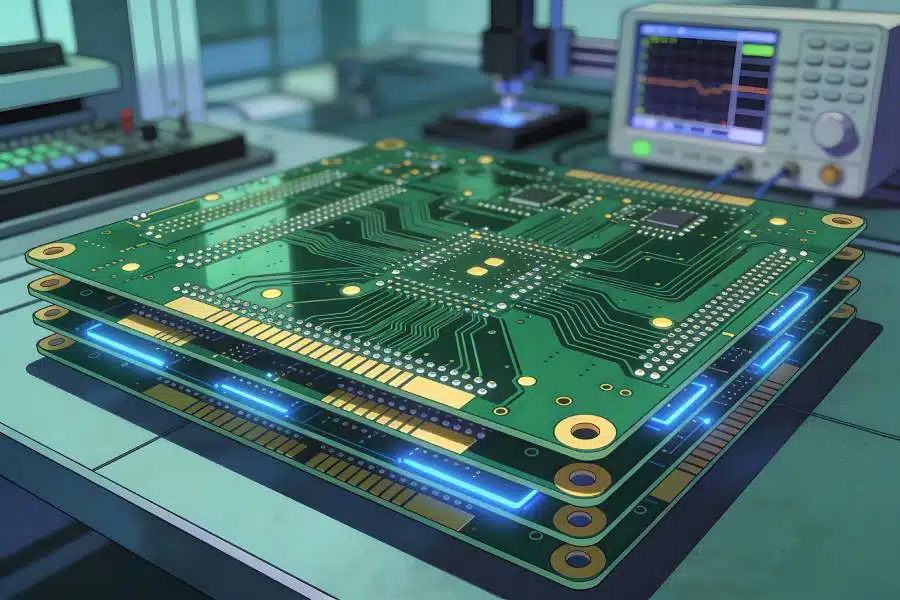
<img src="https://www.gopcba.com/wp-content/uploads/2026/08/SMT-PCB-Assembly.jpg.webp" alt="Plating rack carrying PCB panels into a copper plating tank” />
What a Plating Rack Has to Do
The rack performs three jobs at once. It delivers current, it positions the work so that the field between anode and cathode is as even as the tank allows, and it isolates every surface except the contact point so that metal is deposited on the panel rather than on the frame.
Those jobs conflict. A contact that is tight enough to pass current may damage the copper at the contact point, and a coating thick enough to insulate the frame may also crack and trap solution. Good rack design and steady maintenance resolve the conflict in favour of repeatability rather than of any one requirement.
Contact Points and Contact Resistance
Every contact has resistance, and the voltage lost across it is unavailable to the plating cell. A rack with dirty or corroded tips therefore deposits less copper for the same rectifier setting, and because resistance varies between tips, panels on the same rack can receive measurably different thicknesses.
Contact resistance is checked by measuring the voltage drop between the rack spine and a tip while current flows, or by comparing thickness on panels hung at known positions. Both methods are more reliable than looking at the tips, because a contact can appear clean while an oxide film underneath it holds resistance. Plating failures found this way are described in via plating defect diagnosis.
Coating Damage and Stray Plating
Rack coating, usually a plastisol or a similar dielectric, fails in three ways: it cracks at a bend, it blisters where solution has penetrated under the edge, and it wears thin where panels rub against it. Any exposed metal becomes a cathode and plates copper that should have gone onto the panel.
Stray plating on the rack is self-accelerating. The deposit increases the surface area, which lowers local current density and encourages more deposition, and the nodules that form can touch a panel or shed particles into the bath. A rack that is stripped and re-coated on a schedule avoids the whole sequence.
Current Density, Throwing Power and Hole Coverage
Current density is the current divided by the plating area, and it is the number that decides grain structure and thickness distribution. Because a rack adds area of its own, the effective current density on the work depends on how much of the rack is immersed and how much of it has stray plating.
Coverage of a deep hole depends on both current density and the chemistry that gives the bath its throwing power. A rack that shadows one edge of a panel reduces the local current density there, and a hole in that area will plate thinner and may crack later. Surface distribution checks should therefore compare positions on the rack, not only points on the panel. The evidence for coverage is collected with plating thickness distribution and microsection work.
Rack Cleaning, Stripping and Re-coating
Cleaning removes solution and drag-out between runs, while stripping removes stray plating from the contact area and from any exposed frame. The two operations use different chemistries and must not be confused: a cleaning bath that is asked to strip metal will exhaust quickly, and a stripping bath that is reused as a cleaner will attack the coating.
Re-coating closes the cycle. Tips are masked so that the coating stops short of the contact, the frame is cured at the temperature the material requires, and the finished rack is inspected for pinholes before it goes back into production. A rack that is re-coated but not inspected simply moves the stray plating to a new location.
Rack Loading, Spacing and Shadowing
Panel spacing on the rack controls how evenly the current field reaches the work. Panels hung too close shield each other, and the surfaces that face one another plate thinner than the outer faces. The effect grows with panel thickness and with the height of the rack.
Loading also determines the total area, and therefore the rectifier setting for a given current density. A standard loading pattern, with a defined number of panels and a defined orientation, allows the setting to be repeated from shift to shift. A rack that is loaded differently every time is the reason a tank that ran perfectly yesterday fails a thickness check today.
Rack Maintenance Schedule and Records
The schedule should be built from inspection rather than from the calendar alone. Daily checks cover contact appearance and coating damage on the working faces, weekly checks cover resistance and stray plating, and a full strip and re-coat follows the number of plating cycles the rack has seen.
Records need to identify the individual rack, because a rack number ties a defect to the hardware that produced it. When a thickness problem repeats on the same product but involves different tanks and different shifts, the rack is the first item to check. Test methods for the deposit itself come from the standards published by SMTA.
When a Rack Should Be Retired
Retirement is a decision that should be made on evidence. Persistent contact resistance that cleaning does not reduce, a frame that has been welded or repaired in the current path, and coating that cannot be renewed because the frame surface has become pitted are all end-of-life signals.
A worn rack costs more than its replacement. It produces scrap that is hard to trace, it consumes additive and current that produce no saleable output, and it teaches the line to accept a distribution that no amount of electroplating thickness control can correct. Cracked barrels caused by uneven plating are documented in barrel cracks in plated holes.
Verification and Records
Handling between operations is part of the process, and the damage it causes is often attributed to the operation that preceded it. A change that is not recorded is a change that cannot be explained when the result moves, which is why the record is part of the process.
FAQ
How often should rack tips be cleaned? Tips should be inspected daily and cleaned whenever oxide or stray plating is visible, with a resistance check at least weekly. Cleaning on a fixed interval regardless of condition wastes labour and still misses the racks that need attention.
Can one rack serve several tank types? It can if the coating, the contact material and the loading pattern suit all of them. Where chemistry differs enough to need a different contact material, a shared rack spreads contamination from one tank to the next.
Why does plating thickness vary between panels on the same rack? Current takes the easiest path, so a tip with lower resistance carries more and the panel beside it carries less. Sorting the thickness data by rack position shows the pattern, and measuring the resistance confirms it.