



CAM Engineering: 5 Reviews Before Fabrication
CAM engineering is the step between a finished design and a shop that can build it. The design file arrives as artwork, drill data and a stackup, and CAM engineering turns that into the films, programs and instructions the line will work from. Everything the shop cannot infer has to be added here.
The work is not a formality. Most of the decisions that make a board buildable in volume are made at this desk: how the panel is arranged, how much the etch will move, which apertures change and which features are too close to survive the process.
What CAM Engineering Changes in a Design
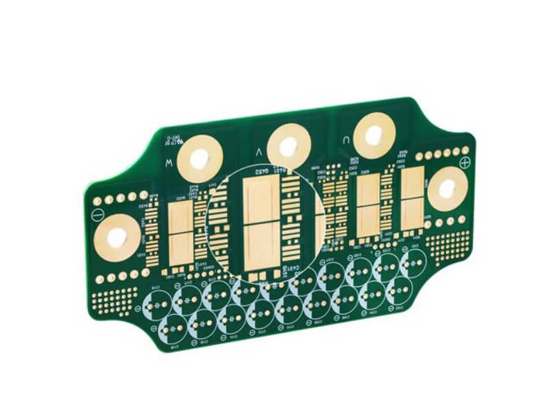
The output is never identical to the input. Pads are adjusted for the process, legend is moved off exposed metal, mask openings are resized and the panel is built around the unit. Each change has a reason, and each reason belongs in the documentation that travels with the order.
The danger is a change made without a record. When a feature is quietly modified to make it buildable, the next order from the same design file will be changed again by a different engineer, and the two batches will not be identical even though they carry the same revision number.
Reading the Design File Before Anything Else
The first pass is a read, not an edit. The stackup, the layer count, the finish and the impedance requirements are compared with what the order says, because a mismatch found here costs a phone call while the same mismatch found on the line costs a batch.
The design file should also be checked against the fabrication drawing, which is the document that states what is actually wanted. Where the two disagree, the drawing normally governs, and the difference should be raised rather than resolved by preference. Our design release notes describe what the drawing should contain.
Annular Ring and Drill Size Checks
An annular ring that is too small for the drill tolerance will break out on some panels and pass on others, which is the worst kind of defect because it survives inspection. The check is arithmetic: pad size minus drill size, divided by two, compared with the allowance for registration and drill wander.
Drill size itself is usually adjusted to allow for plating, since the finished hole is what the component needs. A drill size taken from the design file without that allowance produces a hole that is too tight for the lead, and the assembly line finds it first. Our annular ring notes set out the arithmetic.

Panel Layout and the Tooling That Follows
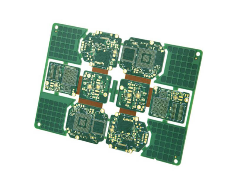
The panel arrangement decides how many units come off a sheet, where the rails sit and how the board is handled on every machine that follows. It also decides the tooling: the drill program runs on a panel, not on a unit, so the spacing between units becomes part of the drill data.
Border area, fiducials, tooling holes and coupon positions are all placed at this stage. A panel that leaves no room for a coupon cannot be certified later, and a panel without tooling holes cannot be located accurately on the drill. Our panelization notes cover the layout choices.
Copper Balance and Etch Compensation
Etch compensation widens a feature to allow for the amount the process will remove, and the amount depends on the copper thickness and the feature density around it. A single compensation value applied across a dense board produces thin traces in the busy areas and heavy traces in the open ones.
Copper balance is the other half of the same question. A side with large planes and a side with a few traces will etch and laminate differently, so the CAM engineer may add a thieving pattern to even the load. That addition changes nothing electrically but improves the yield of the batch.
Solder Mask and Legend Adjustments
Mask openings are usually enlarged relative to the pad so that the mask does not encroach on the joint, and the enlargement has to stop before it exposes the neighbouring trace. The trade off is different on fine pitch parts, where a small opening is better for bridging but raises the risk of mask on the pad.
Legend is adjusted for legibility: text is moved, resized or thinned so that it prints on a line width the screen can hold. Text that sits on exposed metal will not survive, and text that is too fine will be unreadable on the finished board.
Questions That Go Back to the Designer
Some items cannot be resolved without the designer. A missing layer in the stackup, an impedance requirement with no reference plane or a connector footprint that does not match the drawing all need an answer rather than a guess, and the question should be asked before the films are made.
A good query is specific. Naming the net, the layer and the two possible readings makes the answer quick, while a general comment about the design produces a slow exchange and delays the order. The query and the answer both belong in the order record.
Documentation Package for the Shop
The package that goes to the line includes the artwork, the drill program, the rout program, the stackup, the finish, the acceptance class and the special notes. Each item should be versioned with the order, so a reprint can be built from exactly the same data.
Where a customer supplies the acceptance class, it should appear on the traveller rather than in an email, because the inspector works from the traveller. Our fabrication notes list the items that are most often missing from a package.
First Article and the Fabrication Traveller
The first panel is measured against the order, not against the design file alone, because the CAM changes are part of what was ordered. Dimensions, hole sizes, annular ring, mask registration and finish thickness are checked before the balance of the batch is run.
A first article that is signed off without a measurement is only a confirmation that a panel exists. The measurements should be recorded on the traveller, with the instrument and the operator, so that a later query can be answered from the file.
Records and Revision Control
Every CAM change should be recorded against the order and against the design revision. That record is what allows a customer to ask why a batch differs from the previous one and to receive a factual answer rather than an apology.
The design file itself should be stored as it was received, separately from the CAM data that was produced from it. Keeping both makes it possible to rebuild an order years later, which is a requirement in most regulated supply chains. The IPC documentation standards describe the data formats involved.
FAQ
Does CAM engineering change the electrical performance? It should not, but it can affect impedance where trace width and dielectric spacing are adjusted. Any change that touches an impedance controlled net should be calculated and reported rather than left as a process detail.
Who owns the tooling holes and the coupon? The shop places them, and they belong to the panel rather than to the product. The customer should still see the panel drawing, because the coupon is the evidence used to accept the boards and the position affects the unit count.
Can a customer insist on no changes? They can, and the shop should then confirm in writing that the design is buildable as supplied. Where it is not, the choice is a documented deviation or a redesign, and either is better than a silent adjustment on the line.


1 Comment
Step Board: 5 Rules For Cavity Depth Control - Kingda
[…] no longer has to judge its depth against a stack that has already moved. That decision belongs in CAM review, where the stack and the tool path can be checked […]