Micro Drill Small Hole Control in PCB Fabrication: 6 Rules
A micro drill is a bit small enough that its own stiffness becomes a process variable. Below roughly 0.3 mm the shank deflects under the thrust of the drill, the flutes fill faster, and the margin between a sound hole and a broken bit is measured in a few microns of runout. The same machine, the same panel and the same program that produce hundreds of sound holes with a 0.8 mm bit behave differently at 0.2 mm.
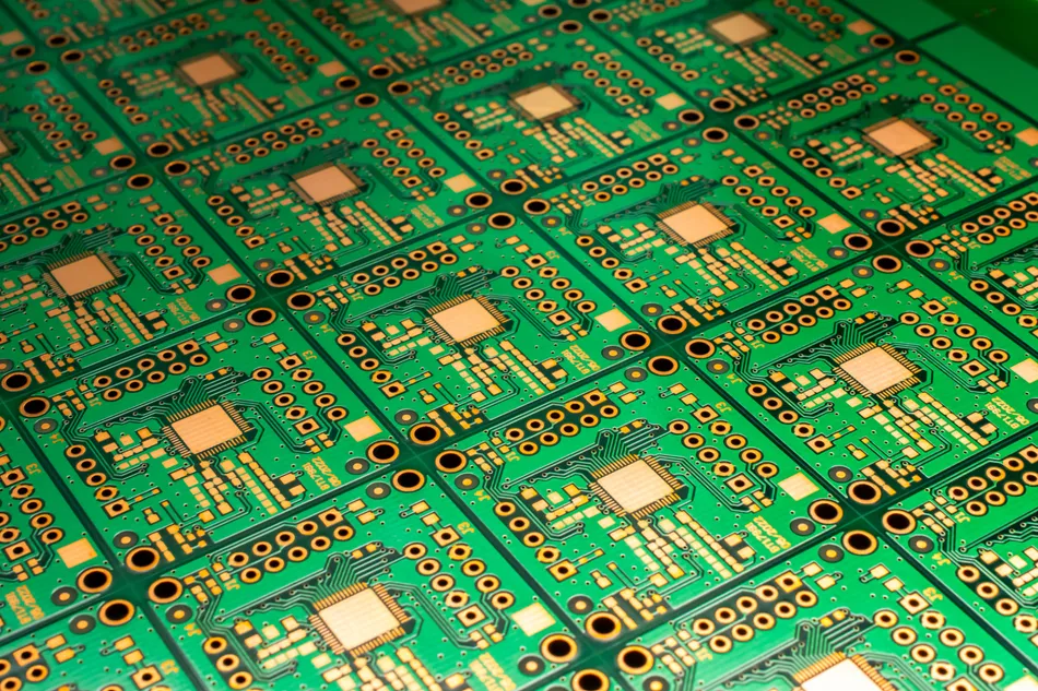
Small holes are used for via-in-pad, for high-density interconnect, for microvias in thin laminates and for the fine arrays in package substrates. Each of those applications has a legend that cannot tolerate a ragged wall, a smear of resin over the inner layer, or a nail head that closes the hole at the surface. Control therefore starts with the bit and the spindle, not with the inspection bench.
Why a Micro Drill Behaves Differently
Stiffness falls with the fourth power of diameter, so reducing a bit from 0.5 mm to 0.25 mm removes almost all of its resistance to bending. The bit then follows the path of least resistance instead of the programmed path, and any runout in the spindle or the collet is copied into the hole wall.
Chip evacuation is the second difference. A small flute has a small volume, and the dust produced by glass-reinforced laminate does not leave the hole as easily as it does from a large hole. When the flutes pack, the bit rubs instead of cutting, the temperature rises and the resin in the wall softens.
The hit count that a bit survives is therefore much lower for a small diameter, and it depends on the stack height, the resin content and the entry material far more than it does for a standard bit.
Spindle Speed and Chip Load
The surface speed of a micro drill falls quickly as the diameter drops, so spindle speed is raised to keep the cutting speed in a sensible range. That is why small-hole spindles run at a hundred thousand revolutions per minute and above, and why the spindle runout specification is as important as the top speed.
Chip load is the thickness of material removed by each cutting edge per revolution, and it is set by the feed rate divided by the number of flutes and the speed. Too high a chip load bends the bit and tears the copper at the hole exit, while too low a chip load rubs the wall and generates heat without removing material. The window is narrow, and it is found by drilling a test coupon and inspecting the wall rather than by calculation alone.
Entry and exit material support the laminate where the bit is least supported. An aluminium entry sheet stops the drill wandering at the surface, and a backing board stops the exit burr that would otherwise lift and tear the copper pad.
Bit Geometry, Runout and Breakage
Micro drills are made with a defined point angle, web thickness and flute geometry for a particular family of laminates. A bit designed for a hard, highly filled laminate will not cut cleanly in a soft one, and the difference shows up as a smear or a rough wall rather than as a break.
Runout is measured on the assembled collet and bit, not on the spindle alone. A collet that has been overtightened, or one with trapped dust, will hold the bit off-centre and produce a hole larger than the bit with a taper on one side. The chisel edge then rubs rather than cuts, and the heat produced is what shortens the bit life.
Breakage usually happens at the start of the hole, where the bit meets the entry material, or at the exit when the last layer lets go. Both points are visible in the drilling data as a step in the spindle load, and that step is the cheapest early warning of a problem.
Records, Regrinding and Hit Count
Every drill is given a life in hits, and the life is set from measured hole quality rather than from a supplier figure. The count should be tracked per spindle and per stack, because one spindle running with a damaged collet can consume a batch of bits in a shift.
Where bits are reground, the reground geometry has to be verified before the bit returns to small hole work, since a regrind that removes the web properly on a large bit may leave a micro drill with an oversized chisel edge. A chip load record per material family keeps the feed and speed decisions traceable.
Hole quality is confirmed by cross-section for plating review, and the relationship between drilling and the resin smear left in the barrel is explained in the desmear notes. Copper coverage in a small barrel is covered in the plating void guide, and the surface finish that follows is described in the immersion tin review.
When a Small Hole Fails in Production
Nail head is the name given to the flare of copper that forms around a small hole when the drilling and plating sequence is not balanced. It appears as a raised ring that reduces the flat area available for the pad, and on a fine pitch array it can be enough to prevent a component from seating. The flare is usually caused by an exit burr that was plated over rather than removed, so the drill program and the backing material are the first places to look.
Wall roughness is the second failure that is specific to a micro drill. A wall that has been rubbed rather than cut shows a helical pattern, and the plating that follows replicates it as a series of thin and thick bands. Those bands concentrate current and stress, and the barrel then fails in thermal stress even though the average copper thickness looked correct on a cross-section.
Where the defect is intermittent, the records usually show it moving with the spindle. Tracking hole quality by spindle, by bit batch and by stack height separates a tooling problem from a material problem, and it turns a scrap report into a maintenance action.
Small hole drilling also consumes entry and exit material faster than large hole work, because each hit removes more of it relative to the hole. The entry sheet is changed on a schedule that follows the hit count, and a worn entry sheet is a common cause of a hole that wanders at the surface while the rest of the barrel is sound.
FAQ
What is the smallest small hole a micro drill can produce reliably? It depends on the aspect ratio more than on the diameter. A shallow 0.1 mm hole in a thin core is routine, while the same diameter through a thick stack is a different problem because the chip has to travel further and the bit has less support.
Should hit count be reset when the stack height changes? Yes. The number of hits a bit survives is a function of how much material it removes, so a shorter stack should be given a proportionally longer life or the bit will be retired with capacity left in it.
Why does the hole come out larger than the bit? Almost always because of runout in the collet or the spindle, or because the bit is deflecting at the entry. Measuring the hole at the top and the bottom of the barrel separates the two causes.