Peck Drilling and Retract Rate Control for Deep PCB Holes
Peck drilling breaks a deep hole into a series of short advances, retracting the bit between them so that chips leave the hole instead of packing around the flutes. It is the standard answer when the aspect ratio climbs past roughly eight to one, when the stack contains a material that produces stringy debris, or when the hole runs through a resin-rich laminate that smears under heat. The parameters that decide whether it works are the peck depth, the drill retract rate, the spindle speed and the evacuation path, all of which interact with the chip load the tool is asked to carry.
When Peck Drilling Is Needed
A hole is drilled in one pass while the flutes can still lift debris out of the hole as the bit advances. Once the depth exceeds about eight times the diameter, the flutes fill before they clear the surface, and the debris is reground between the margin and the wall. At that point the hole wall begins to show smearing and the drill temperature climbs.
Deep holes in high-layer-count boards, thick backplanes and holes drilled after lamination are the usual candidates. So are stacks containing ceramic-filled laminates and thick aluminium entry foils, both of which produce hard debris that acts as an abrasive if it stays in the hole. Shallow holes in thin two-layer material rarely benefit, because the retract strokes cost cycle time without changing the result.
Chip Evacuation and Flute Loading
Evacuation depends on the volume of the flute space compared with the volume of material removed per advance. A peck that removes more than the flute can hold leaves debris in the hole regardless of how many retracts follow. Peck depth is therefore set as a fraction of the flute length, commonly one to two times the diameter for the first peck and a smaller step afterwards as the wall friction grows.
Spindle speed and feed rate decide the shape of the debris. A feed that is too light rubs rather than cuts and produces fine powder that packs tightly; a feed that is too heavy loads the cutting edges and lifts the drill in the collet. The window is usually expressed as a chip load per revolution, and the value that works for one laminate is not necessarily right for another.
Retract Rate and Hole Wall Quality
The drill retract rate is the speed at which the bit leaves the hole between pecks. Retracting too quickly drags debris up the wall and scores it, while retracting too slowly allows the flutes to dwell and re-cut the same material. On most machines the retract is set above the drilling feed rate, in the region of 200 mm/s to 400 mm/s, with a short dwell at the bottom of each peck to let the spindle clear.

Wall quality is judged on a microsection. A good pecked hole shows a uniform wall with no smeared resin, no nail-head or hourglass profile, and no debris trapped at the interface with the copper foil. When smear is visible the usual cause is a peck that is too deep for the flute, not a retract that is too fast.
Hit Count, Tool Wear and Regrind
Every retract puts the drill through a small thermal and mechanical cycle, so a pecked hole costs more tool life than a straight hole of the same depth. Hit counts for deep holes are commonly set at half the value used for shallow work, and the count is monitored per drill rather than per panel so that a worn tool is replaced before it produces a run of marginal holes.
Regrind changes the geometry that the parameters were set against. A drill that has been sharpened twice has a different web thickness and a shorter flute, so the peck depth derived from flute length has to be recalculated. Tracking the number of regrinds against the hole quality of each tool is the only way to set a sensible discard point.
Backup and Entry Material Interaction
Entry material controls the top of the hole and backup material controls the bottom. A hard entry foil reduces burring but can shed debris into the flutes, while a soft backup allows the drill to push material ahead of it and form a burr on the exit side. The pair has to be chosen together with the peck parameters rather than inherited from a different product.
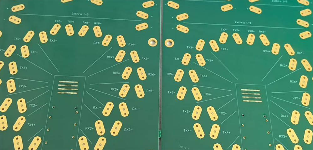
Where debris collects between the backup sheet and the bottom of the panel, the last peck tends to trap it, and the exit hole shows a ring of compressed material. Increasing the retract dwell at the bottom, or reducing the final peck depth, usually removes it without changing anything else in the program.
Drill Breakage, Detection and Recovery
Breakage in a pecked hole is most often caused by a drill that has lost its edge, by debris jamming the flute on the way out, or by a spindle that cannot hold speed under load. The break is usually detected by a vacuum or pressure sensor on the spindle rather than by the operator, and the machine should stop the panel rather than continue drilling the remaining holes with a missing tool.
Recovery matters because the broken fragment stays in the hole or under the panel. The panel has to be removed from the stack, the fragment located, and the position examined before the hole is re-drilled, usually at a slightly reduced feed. Re-drilling without clearing the fragment is the common cause of a cracked wall or a damaged drill in the same position.
Parameter Windows by Aspect Ratio
Aspect ratio, the finished hole depth divided by the drill diameter, is the single best guide to the parameter set. Up to about six to one a straight drill works; between six and twelve to one a two or three peck cycle is typical; above twelve to one the cycle becomes longer, the retract rate is reduced, and the feed per revolution is dropped to keep the debris small enough to clear.
These are starting points rather than limits, and the aspect ratio of the finished hole is not the same as the ratio during drilling, because the drill point and the backup sheet add depth. The value that matters is measured from the surface of the entry material to the bottom of the drill travel.
Machine Capability and Spindle Response
Peck cycles demand more from the z-axis than straight drilling. The spindle has to accelerate and decelerate cleanly at every reversal, and a machine with a slow z-axis cannot follow a short, fast peck without overshooting and re-cutting the bottom of the hole. On older machines the practical fix is a longer peck at a lower retract rate, not a tighter program.
Spindle runout, vacuum flow and collet condition all show up in deep holes first, because the tool has less support than at the surface. Recording runout at the collet, along with the vacuum reading at the spindle, turns an intermittent hole wall problem into something that can be traced to a specific maintenance action.
Verification by Microsection
The final check on a pecked hole is a microsection taken through the hole axis so that the wall, the smear and the copper interface are all visible in one view. Preparation matters here as much as the section itself, and the standard microsection methods apply: cast the sample, grind in steps, keep the cutting direction away from the copper, and examine before and after etching.
Results should be recorded per drill and per parameter set so that a change in the wall can be linked to a change in the program. Comparing a good lot with a suspect lot side by side is more informative than judging a single section against a written standard. Where the wall is marginal, a different drill position check on the same panel tells whether the cause is the peck or the entry of the tool.
FAQ
What peck depth should be used for a deep hole? Start at one to two times the drill diameter for the first peck and reduce the following steps, so that the debris produced per advance stays below the capacity of the flute. The correct value is confirmed by sectioning a hole and looking for trapped debris.
Does a faster retract always give a cleaner hole? No. A retract that is too fast drags debris along the wall and scores it, and one that is too slow lets the flutes dwell and re-cut the material. The useful range is usually 200 mm/s to 400 mm/s, set against the drilling feed.
Why does hole quality drop after a drill is reground? Regrinding shortens the flute and changes the web thickness, so a peck depth derived from the original flute length no longer clears the hole. Recalculate the peck depth and reduce the hit count when a tool is returned from sharpening.