Panel Edge Trimming: 5 Rules for Clean, Damage-Free Edges
Panel edge trimming looks like a simple cut, yet the edge it leaves influences everything that follows. A rough edge sheds copper slivers into the plating line, a burr traps chemistry in the rinse, and a delaminated edge shows up as a reject after thermal stress. The operation also generates the dust that contaminates clean areas if it is not captured at the source.
What Panel Edge Trimming Has to Achieve
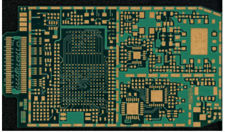
The edge must be dimensionally correct, free of burrs and free of delamination. It must also be consistent, because downstream tooling locates panels by their edges. A panel trimmed to the wrong size jams conveyors, sits badly in plating racks and misaligns in test fixtures. Dimensions should be checked with the panel at room temperature, since laminate grows in a warm workshop.
Edge quality is judged on both copper and laminate. Copper that smears over the laminate leaves a conductive path that can bridge later, while laminate that chips exposes glass fibers that absorb chemistry. Both defects are visible under low magnification and should be part of the inspection standard. Panel edge quality should be defined with photographs showing acceptable and unacceptable examples, because written descriptions leave too much room for interpretation.
Cutting Methods and Their Edge Quality
Routing with a carbide cutter is the most common method and gives good edge quality when the tool is sharp and the feed is correct. Shearing is fast but tends to leave a slightly deformed edge and produces burrs on ductile materials. Choose a method that keeps the cut in one pass, because re-cutting an edge often does more damage than the first cut. Scoring works for straight lines but limits the shapes it can produce.
Waterjet and laser cutting avoid mechanical stress but introduce their own issues, including heat affected zones and moisture that must be removed before plating. Select the method by product requirement rather than by habit, and document the choice in the traveler. Tools used for one method should never be borrowed for another, because a cutter set up for routing performs poorly on a shear.
Edge Burr Removal and Surface Finish
Edge burr removal is normally done with a brushing or deburring step after routing. The goal is to remove the raised copper without rounding the edge profile or driving particles into the laminate. Brush pressure, speed and abrasive grade all decide whether the result is clean or burnished. Replace brushes on a measured wear interval rather than when they stop working, since worn brushes polish burrs instead of removing them.
Verify burr removal under magnification rather than by touch alone. A smooth-feeling edge can still carry a thin copper lip that survives cleaning and creates a short after assembly. Our note on deburring and brushing covers the parameters that keep this step under control.
Edge Delamination and Fiber Pullout
Edge delamination happens when the cutting forces exceed the bond strength between layers. A dull cutter, excessive feed rate or a cold panel all increase those forces. The defect often appears as a thin separation only a few thousandths deep, which thermal stress expands into a visible blister.
Fiber pullout is the same problem at the micro level, where glass bundles are torn from the resin. Inspect a sample edge under magnification after any tool change, and include the check in the first article inspection rather than waiting for a customer return. Store sample edges from good production as a visual reference so the judgment does not depend on the person holding the microscope.
Routing Tool Condition, Feed Rate and Spindle Speed
Routing tool condition is the single largest influence on edge quality. Measure tool wear on a schedule, track the number of panels cut with each tool, and replace on a count rather than on a feeling. A dull tool raises cutting temperature and smears copper instead of cutting it.
Feed rate and spindle speed must match the tool and the material. Fast feed with low spindle speed produces chips and delamination, while slow feed with high speed overheats the laminate. Vacuum dust extraction is part of the same setup, as described in our guide to drill vacuum dust extraction.
Handling After Trimming and Edge Inspection
Handle panels by the edges only with clean gloves, and stack them with interleaves to prevent one panel edge from nicking the next. Trimming produces sharp corners that damage neighbouring panels during transport, so edge protection is a handling requirement, not a luxury.
Inspection should check edge straightness, burr condition, delamination and dimensions. Sample enough panels to catch a drifting tool, and record the results by lot. Where the same defect repeats at the same location, the fixture or tool holder is the likely cause. Keep a marked-up panel showing where each defect type appears, because location is often the fastest route to the cause.
Dust Extraction and Contamination Control
Dust extraction must capture particles at the cutter, not from the room. A hood that leaks lets conductive dust settle on nearby surfaces, including finished panels waiting for packing. Copper dust in particular causes shorts that appear only at final test.
Empty collection systems before they are full, because a saturated filter releases dust back into the process area. Keep trimming operations away from plating and imaging rooms, and monitor the area with a simple settle plate check if contamination complaints recur. Extraction ducting should be inspected for leaks at joints, since a small leak near the cutter is worse than a distant one.
Tolerance Control and Dimensional Checks
Dimensional checks should use the same datum the customer uses. Measure panel length, width, corner radii and tooling slot positions against the fabrication drawing, and record the values with the ambient temperature, since laminate dimensions change with humidity.
Trend the measurements so tool wear becomes visible as a slow drift. Check the tooling slot position with a gauge every shift, because that feature controls alignment through the rest of the process. Panels that pass individually but trend toward a limit will fail after a material change, and the trend is the only warning you get. Related cutting wear control is covered in our note on v-score blade life control.
Records and Preventive Maintenance
Keep a maintenance log for spindles, collets, brushes and extraction systems, with the same discipline used for any other process tool. Collet runout in particular grows slowly and produces edge defects that look like material problems.
Review the log against defect data monthly, and adjust the replacement interval when the data says so. Acceptance criteria for finished board edges are defined in standards from IPC, and they give inspection a common reference. Cleaning after trimming belongs in the same plan, as described in our guide to panel cleaning before plating.

FAQ
What causes burrs during panel edge trimming? A dull cutter, excessive feed rate or a tool running at the wrong speed are the usual causes. Check tool wear count first, then verify feed and spindle settings against the supplier recommendation.
How can edge delamination be detected before final test? Inspect a sample edge under magnification after each tool change, and include the check in first article inspection. Thermal stress screening later will amplify any separation, so catching it at the router saves a full lot.
Why is dust extraction important at the trimming step? Copper dust is conductive and settles on nearby surfaces, where it causes shorts that appear only at test. Capture dust at the cutter, empty collection systems before they saturate, and keep the area away from imaging and plating.