AOI False Calls: Chasing the Cause, Not the Threshold
False calls are the tax an automated optical inspection line pays for its sensitivity, and the usual response is to widen a tolerance until they stop. That response works in the short term and it is almost always the wrong one, because the tolerance that stops flagging a slightly low component also stops flagging a component that has begun to lift. Reducing false calls properly means finding out why a good board looks bad to the machine.
The distinction that matters is between a call that is wrong about the board and a call that is wrong about the process. A machine that flags a solder joint which is actually acceptable is producing a false call, and a machine that flags nothing while joints lift is producing escapes. Both live inside the same program settings, which is why tuning has to be done with data rather than with patience.
What a False Call Actually Is
A false call is a disagreement between the machine decision and the truth about the assembly. The truth is established by a human at a verification station, and that human is part of the measurement system. If the operator accepts a board that is marginally out of specification, the call is recorded as false when it was in fact correct, and the program is then tuned against a wrong reference.
The categories worth separating in a log are the wrong decision about a good board, the wrong decision about a defective board, and the case where the machine could not decide and referred the image to a person. Counting them together gives a number that cannot be acted on. Counting them separately shows immediately whether the issue is sensitivity, stability or the boundary definition itself.
The Cost of Raising the Threshold
A program tolerance is a window around a nominal value. Widening it moves the decision boundary, and the false call rate falls while the escape rate rises. The relationship is not linear: most of the reduction comes from the first small widening, and most of the escape increase comes from the same region, because the boards that sit near the boundary are the ones that are drifting.
The cost also appears later. A tolerance that is widened to clear a single bad week stays in the program, and the drift that caused the week is never investigated. The correct move is to capture the flagged images, classify them, and look for the common feature. Only after the cause is known is it reasonable to decide whether the boundary or the process should change.
Lighting and Its Stability
Almost every false call on a shiny solder joint is a lighting problem. A dome, a ring and a set of angled bars illuminate a joint from different directions, and the ratio between them is what the program uses to describe a three-dimensional shape on a two-dimensional image. A lamp that has aged, a diffuser that has yellowed or an LED that has failed changes that ratio and moves the decision boundary for every joint on the board.
Lighting stability is therefore a maintenance item with a number attached. The intensity of each channel is measured on a schedule against a reference target, the diffusers are cleaned with the rest of the machine, and the lamp hours are recorded. A machine that is calibrated for position but not for light will drift into false calls and escapes without any mechanical symptom.
Camera, Optics and Resolution
Resolution sets the smallest feature the program can distinguish, and it is a function of the camera, the lens and the field of view. A machine run at a wide field of view to raise throughput has fewer pixels across a small chip part, so its measurement of a shifted or a low component is noisier. The same part imaged at a narrower field of view produces a more stable measurement at the cost of more passes.

Focus is the other half of the optics. A board that sits at a different height than the calibration target is imaged with less contrast, and a low contrast edge is measured with more scatter. The height of the assembly is set by the board thickness and by the reflow process, and the connection to profile control is described in the notes on warpage control.
Reference Images and Teaching Quality
The program learns what good looks like from the images loaded as references. Where those images were taken from a first article that was itself marginal, the program has learned a marginal target. Where they were taken from a single board, the program has no idea how much variation is normal. A reference set built from several boards at the edges of the process window produces a more realistic boundary.
Teaching has to be repeated after any change that alters appearance rather than geometry. A new paste lot with a different flux colour, a new solder mask batch or a new finish changes the contrast of the image and therefore the measurement. The fiducial and alignment side of the same discipline is covered in the notes on fiducial teaching and vision alignment.
Board Height, Warpage and Focus
Warpage moves the board in the direction the machine cannot see. A board that bows between supports presents its centre at a different height from its edges, so the focus and the apparent size of every feature change across the panel. A program taught on a flat panel will call the middle of a bowed panel wrong, and the calls will be clustered rather than random.
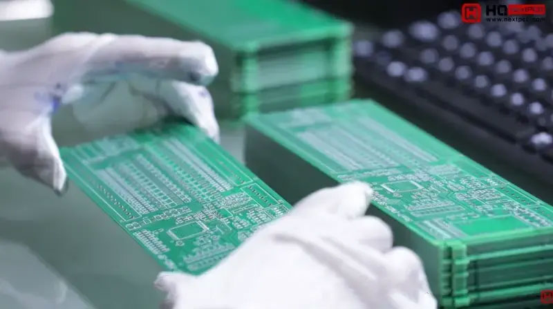
The tell-tale for this cause is the distribution of the calls. False calls that concentrate on one area of the panel, or that follow the pattern of the support fixtures, point to height. Checking the board on a flat reference surface, and comparing the reflow support strategy with the placement of the calls, is usually enough to confirm or eliminate it.
Component and Paste Variation
Parts themselves vary. The same chip resistor from two suppliers can have a different body colour and a different marking, and a part with a chamfered edge presents a different profile to the camera. Paste deposits vary in volume and in surface texture, and a dull, grainy deposit scatters light differently from a smooth one, which changes the apparent fillet. The link between deposit volume and joint appearance is set out in the notes on paste volume measurement.
When a false call rate rises after a component or a paste change, the cause is usually in the appearance model rather than in the geometry. The fix is a re-teach with samples of the new material rather than a wider tolerance. Where the supplier changes repeatedly, the program should carry separate models per supplier part number.
Escape Rate When Tuning
Every tuning decision should be accompanied by a check on escapes. The practical method is a boundary board: a sample with deliberately induced defects at the edge of the acceptance limit, run through the line at intervals. If a widened tolerance stops flagging that board, the escape rate has changed and the tuning has gone too far.
X-ray or a functional test can be used to confirm the escapes on production units where a boundary board is not available. The data from those checks should feed back into the program settings, and the version of the program should be recorded so that a change in the call rate can be dated. Without a version history the cause of a change is impossible to establish.
Verification Station and Records
The verification station is where the truth is assigned, so it deserves the same attention as the machine. The operator needs a clear image, a reference image, a written acceptance criterion and enough time. A station that shows only a small thumbnail, or that requires the operator to judge a joint against memory, will produce a classification that is not repeatable and a false call log that is not trustworthy.
The record should hold the image, the program version, the operator decision and the reason. With those fields a weekly review can rank the causes of false calls and direct the effort: lighting, teaching, height or materials. That review is what turns a false call problem from an argument about thresholds into a maintenance and process plan.
FAQ
What false call rate is normal? It depends on the product and on the program age, so the useful figure is the trend rather than an absolute value. A rate that doubles after a maintenance event is the signal to investigate.
Does a better camera remove false calls? It reduces the measurement noise, which helps at the limit. It does not fix a reference set built from a marginal board or a lighting channel that has drifted.
Should the tolerance be widened at all? Only after the flagged images have been classified and the cause is understood. Widening a tolerance to clear a process drift is how escapes get written into a program.