Component Placement Vision Alignment: Fiducials and Offset Control
Vision alignment is the step in which the placement machine locates the board and the component optically before the head releases the part. It is the only closed-loop correction available during component placement, and it determines the placement offset that remains after the machine has done its best work. A machine with excellent mechanics but weak optical performance will still place parts outside the tolerance the design assumes.
The loop has two halves. Board alignment uses fiducials to establish the coordinate frame of the panel, and component alignment uses a camera to find the body or the leads once the nozzle has picked the part. Both halves must be calibrated against the same reference, or the errors add rather than cancel.
The Vision Alignment Loop
The sequence begins when the panel reaches the placement position and the camera images two or more fiducials. The machine calculates translation and rotation and, on some platforms, scale and skew as well. The nozzle then picks the component, and either the same camera or a dedicated upward-looking camera images the part while it sits on the nozzle.
The two measurements are combined into an offset that the gantry applies during travel. Because the correction is applied in real time, the dominant error sources are the accuracy of the fiducial detection and the repeatability of the pick, not the absolute accuracy of the gantry itself. A useful check is to place a single 0402 part at the centre and at the four corners of a panel, then compare the residual offset. A difference of more than about 0.025 mm between corners points to a fiducial or lighting problem rather than to gantry scaling.
Fiducial Design and Placement
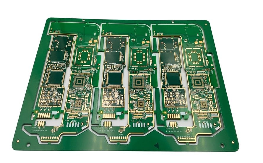
Fiducials should be round, free of solder mask and at least 1 mm in diameter, with a clear area around them roughly equal to the mark diameter. The contrast between a bare copper or gold dot and the surrounding laminate is what the camera actually measures, so mask bleeding over the edge degrades detection more than a small reduction in size does.
Three fiducials are the practical minimum for a panel, placed as far apart as the layout allows and never in a symmetric line that leaves rotation ambiguous. A mark that is too small, or one sitting under a partially open mask window, produces a weak edge that the algorithm can lock onto at the wrong side. On a multi-up panel, every circuit that will be placed should have a local fiducial within about 25 mm of each fine-pitch device. The underlying method is described in this note on fiducial teaching.
Lighting and Contrast
Fiducial detection is a contrast measurement, so the illumination must be stable. Ageing LEDs, a dirty lens or a partially blocked ring light change the grey level of the mark and shift the calculated centre by a fraction of a pixel. Over thousands of placements that bias appears as a systematic offset in one direction.
Lighting is normally verified with a reference target at the start of a shift, and the grey-level histogram is compared with the commissioning record. A drift of more than about ten percent in the peak value is usually enough to justify cleaning or replacing the illumination module. Both the mark and the laminate around it should be sampled, because the threshold between the two is what the algorithm actually uses.
Nozzle and Spindle Calibration
The pick event is where repeatability is won or lost. A nozzle that is worn, contaminated or slightly bent will place the component differently depending on how it seated, and no amount of optical correction can fix a variation that changes between picks. Spindle runout and nozzle tip condition are therefore part of the alignment chain.

Calibration of the nozzle tip position relative to the camera uses a glass target or a dedicated fixture. The result is a per-nozzle offset that should be re-measured after any nozzle change, after a head collision, and on a scheduled interval of typically one to four weeks. Routine care is covered in this guide to vacuum nozzle care.
Measuring Placement Offset
Offset is measured after reflow, because the paste surface and the surface tension of the joint move the component slightly during melting. An X-ray or optical system measures the centroid of each lead or ball relative to the pad centroid, and the result is reported as a two-dimensional offset plus a rotation.
The measurement must be taken on the same board type and panel position used for the process capability study. A single panel gives a snapshot, while a capability figure requires at least 30 components of the same package spread across several panels built with the production settings. Offset should be recorded per package type rather than averaged across the whole board, since a single global number hides the packages that are genuinely at risk.
Common Alignment Faults
The most frequent fault is a fiducial recognised at the wrong edge because mask residue or a scratch creates a competing contrast edge. The reported centre then shifts by half the mark diameter, and the whole panel is placed off-centre in a consistent direction that repeats on every board.
The second frequent fault is a nozzle picking the component off-centre because the feeder pocket is worn or the tape is not seated. The camera sees the part on the nozzle and corrects to that position, so the placement looks acceptable while the body is rotated slightly relative to its leads. Checking the feeder pick position with a tape sample separates the two causes quickly.
Placement Accuracy and Capability
Placement accuracy is expressed as a Cpk against the design tolerance, usually with a target of 1.33 or better for fine-pitch devices. The figure should be produced with the production program, the production nozzles and the production paste, because each of those factors contributes to the observed spread. Offset in X and Y should be reported separately, because a machine can be well centred in one axis and marginal in the other.
When Cpk is below target, the usual order of investigation is fiducial quality, then nozzle condition, then feeder pick position, and only then machine calibration. Adjusting the machine first often masks a mechanical problem that returns within a few shifts. Related measurement practice is described under placement offset control.
When to Re-Verify
Re-verification is triggered by a nozzle change, a feeder change, a program edit, a machine move or a repair to the head. It is also worth performing after a change of paste or stencil, because the printed deposit position affects the final offset even though the optical system itself is unchanged. Records should show the date, the nozzle set, the measured offset and the person who released the line.
A short verification of one panel carrying a known fine-pitch device takes a few minutes and catches most regressions. Full capability studies can then be reserved for new products and for the periodic schedule defined in the control plan.
FAQ
How many fiducials should a panel have? At least three global fiducials, plus one local fiducial near each fine-pitch device on multi-up panels.
Can vision alignment fix a warped board? Only partly. It corrects the local frame, but a board that is not flat changes the standoff and the printed deposit position.
Is placement offset measured before or after reflow? After reflow, because self-alignment during melting moves the component relative to the printed paste.