How to Solder Wires to a PCB: PCB Design, PCB Manufacturing & Soldering Guide
Whether you work in electronics prototyping, PCB repair, product development, or commercial electronics assembly, knowing how to properly solder wires to a printed circuit board (PCB) is an essential skill. A properly soldered wire can provide a low-resistance electrical path while also offering sufficient mechanical strength to withstand normal handling, vibration, and repeated operation.
Although soldering a wire to a PCB may seem simple, reliable results depend on much more than simply melting solder onto a connection. The correct wire type, wire gauge, solder alloy, flux, soldering iron tip, PCB pad condition, heating technique, and strain-relief method all influence the final connection.
This PCB soldering guide explains the complete process of soldering wires to a circuit board, including wire selection, solder and flux selection, PCB preparation, soldering techniques, joint inspection, troubleshooting, strain relief, and safety precautions.
What Is PCB Wire Soldering?
PCB wire soldering is the process of permanently attaching an electrical wire to a conductive pad, plated through-hole, terminal, or other connection point on a printed circuit board using molten solder.
The objective is to create both:
- A reliable electrical connection with low and stable resistance
- A mechanically stable connection that can withstand normal operating conditions
Proper wire soldering is important because a weak solder joint can result in intermittent signals, voltage drops, increased resistance, localized heating, or complete circuit failure.
Unlike electronic components with rigid leads or solder terminals, wires are flexible and can move during installation and operation. Therefore, the soldered connection must be designed and assembled carefully to prevent mechanical stress from being transferred directly to the solder joint.
Why Is Wire Soldering Important?
A solder joint connects the wire electrically to the PCB while also securing it mechanically.
However, solder should not be considered a substitute for proper mechanical strain relief. If a wire is repeatedly pulled, bent, or vibrated at the solder joint, the connection may eventually crack or the PCB pad may lift from the board.
This is particularly important in:
- Portable electronics
- Automotive electronics
- Industrial control equipment
- Power supplies
- Battery-powered products
- Test equipment
- Prototypes and development boards
- Frequently serviced equipment
Through-Hole vs. Surface Soldering
Wires can generally be connected to PCBs using either through-hole or surface-pad connections.
Through-hole soldering involves inserting the wire through a plated hole and soldering it to the hole and surrounding pad. When properly designed, this method can provide strong mechanical retention.
Surface soldering involves attaching the wire directly to a PCB pad without passing it through a hole. It is useful when board space is limited or when no suitable through-hole connection is available.
For applications involving significant mechanical stress, a through-hole connection combined with additional strain relief is often preferable when the PCB design permits it.
Types of Wires Used for PCB Soldering
Selecting the right wire is just as important as choosing the correct solder.
Different wire constructions offer different levels of flexibility, mechanical durability, current-carrying capability, and solderability.
| Wire Type | Best Use | Advantages | Limitations |
|---|---|---|---|
| Solid wire | Fixed connections, prototyping | Easy to position and solder | Can fatigue after repeated bending |
| Stranded wire | Power cables, moving applications | Flexible and durable | Requires careful preparation and tinning |
| Tinned copper wire | Humid or corrosive environments | Improved oxidation resistance and solderability | May cost slightly more |
Solid-Core Wire
Solid wire consists of a single copper conductor. It is easy to strip, position, and solder, making it useful for fixed connections, laboratory work, and prototyping.
However, solid wire is less suitable for applications involving repeated bending because mechanical fatigue can eventually cause the conductor to break.
Stranded Wire
Stranded wire consists of multiple fine copper strands twisted together.
It is widely used in electronics because it offers much greater flexibility than solid wire. This makes it suitable for portable devices, cables, moving assemblies, and applications where vibration or repeated movement is expected.
When soldering stranded wire, the exposed strands should be properly organized and, where appropriate, lightly tinned before making the connection.
Tinned Copper Wire
Tinned copper wire has a thin tin coating over the copper conductor.
The coating helps reduce surface oxidation and can improve solderability. Tinned copper wire can therefore be useful in applications where long-term solderability and environmental resistance are important.
Choosing the Correct Wire Gauge
Wire gauge should be selected according to the electrical and mechanical requirements of the application.
Current capacity, allowable voltage drop, conductor length, temperature rise, insulation rating, flexibility, and PCB pad dimensions should all be considered.
As a general starting point:
| Application | Typical Wire Gauge |
|---|---|
| Signal wiring | 26–30 AWG |
| Sensor connections | 24–28 AWG |
| Low-power circuits | 22–24 AWG |
| Power distribution | 18–22 AWG |
| Higher-current connections | 14–18 AWG |
These ranges are only guidelines. The appropriate wire size must ultimately be determined by the actual current, conductor length, temperature, insulation, installation conditions, and applicable design requirements.
For high-current connections, using a wire that is too small can increase voltage drop and heating. Conversely, an excessively large wire may place unnecessary mechanical stress on a small PCB pad and make soldering more difficult.
Tools Required for Soldering Wire to a PCB
Reliable PCB Assembly and repair work requires the right tools.
Temperature-Controlled Soldering Iron
A temperature-controlled soldering iron is preferable to an uncontrolled iron because it allows the operator to maintain an appropriate working temperature for the solder alloy and application.
The required temperature depends on the solder alloy, flux, thermal mass of the connection, PCB construction, and component sensitivity. There is no single temperature that is correct for every PCB soldering operation.
Solder Wire
Electronic-grade solder wire is available in different diameters.
A diameter around 0.6–1.0 mm is suitable for many hand-soldering applications, while thinner solder can provide better control for small pads and fine connections.
Flux
Flux helps remove surface oxides and promotes solder wetting.
Rosin-core solder already contains flux, but additional liquid or gel flux can be useful when working with oxidized surfaces or difficult-to-solder connections.
Wire Preparation Tools
Useful tools include:
- Wire strippers
- Flush cutters
- Needle-nose pliers
- Tweezers
- PCB holders
- Helping hands
- ESD-safe work mats
These tools make it easier to prepare the wire and keep the PCB and wire stable during soldering.
Inspection and Testing Equipment
A digital multimeter can be used to check continuity and identify unintended shorts.
A magnifying glass or inspection microscope can also help identify:
- Poor wetting
- Cracks
- Solder bridges
- Excessive solder
- Damaged pads
- Stray wire strands
Choosing the Right Solder and Flux
Selecting an appropriate solder and flux is an important part of achieving a reliable solder joint.
Leaded Solder
Traditional tin-lead alloys such as 60/40 Sn-Pb have relatively low melting temperatures and good wetting characteristics.
They are still encountered in repair, education, prototyping, and other applications where their use is legally permitted.
Lead-Free Solder
Lead-free solder is widely used in commercial electronics to comply with environmental requirements such as RoHS.
Common lead-free alloys include tin-silver-copper (SAC) formulations.
Lead-free solder generally requires a higher processing temperature than traditional Sn-Pb solder, so the soldering process must be controlled appropriately.
Rosin Flux
Rosin-based flux is commonly used for electronics hand soldering.
It helps remove oxides and improve solder wetting while generally leaving manageable residues.
No-Clean Flux
No-clean flux is formulated to minimize residues and, depending on the specific formulation and application requirements, may not require post-solder cleaning.
However, “no-clean” does not mean that residues are automatically harmless in every application. The flux manufacturer’s specifications and the product’s reliability requirements should be followed.
Water-Soluble Flux
Water-soluble fluxes generally provide strong oxide removal capabilities but normally require appropriate post-solder cleaning.
Remaining residues can cause reliability problems if they are not removed according to the flux manufacturer’s requirements.
Selecting the Correct Soldering Iron Tip
The soldering iron tip should match the size and thermal requirements of the connection.
A fine conical tip can be useful for small connections, while a chisel-style tip can provide better thermal transfer to larger pads and heavier wires.
The goal is not simply to use the smallest tip possible.
An appropriately sized tip can transfer heat more efficiently and reduce the amount of time the PCB must be exposed to elevated temperature.
Preparing the PCB and Wire
Preparation is one of the most important stages of PCB Soldering.
A clean PCB pad and properly prepared wire allow solder to wet the surfaces more effectively and help produce a reliable electrical and mechanical connection.
1. Clean the PCB Pad
PCB pads should be free from oil, fingerprints, dust, and other contaminants.
Isopropyl alcohol can be used when appropriate for the PCB surface and manufacturing requirements.
Avoid unnecessarily aggressive mechanical cleaning that could damage the pad or solder mask.
2. Strip the Wire Correctly
Use an appropriate wire stripper to remove only the required amount of insulation.
For many small wire connections, approximately 3–5 mm of exposed conductor may be sufficient, but the actual stripped length should match the pad size and connection design.
Do not nick or cut the copper strands during stripping.
Damaged strands reduce the effective conductor cross-section and may weaken the connection.
3. Twist and Tin Stranded Wire
For stranded wire, organize the exposed strands and lightly twist them together.
Applying a small amount of solder to the strands can hold them together and make positioning easier.
However, excessive solder wicking into the flexible portion of the cable can create a rigid section that becomes vulnerable to fatigue. The transition between the tinned section and flexible cable should therefore be considered when designing strain relief.
4. Apply Flux When Necessary
Apply an appropriate amount of flux to the wire and PCB pad.
Flux helps remove surface oxides and improves solder wetting.
Avoid excessive flux because unnecessary residues can create additional cleaning requirements.
5. Secure the PCB
Place the PCB in a suitable holder or fixture before soldering.
The board and wire should remain stable while the solder joint is forming and cooling.
Movement during solidification can contribute to poor joint formation and mechanical defects.
Step-by-Step Guide: How to Solder a Wire to a PCB
Learning how to solder a wire to a PCB is easier when the process is divided into repeatable steps.
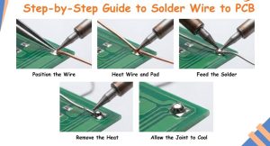
Step 1: Position the Wire
Place the prepared wire against the PCB pad or insert it through the appropriate plated through-hole.
The wire should be mechanically stable before soldering begins.
Step 2: Heat the Joint
Place the soldering iron tip so that it transfers heat to both the wire and PCB pad.
The goal is to heat the connection sufficiently for the solder to wet both surfaces.
Avoid relying on the soldering iron to melt solder without properly heating the joint.
Step 3: Feed the Solder
Once the joint reaches an appropriate soldering temperature, feed solder into the heated connection rather than directly onto the iron tip.
The solder should melt because of the heat of the joint and flow over the relevant surfaces.
Use only enough solder to form the required joint.
Step 4: Remove the Solder and Iron
Withdraw the solder wire first and then remove the soldering iron.
Try to keep the wire and PCB stationary while the solder solidifies.
Step 5: Allow the Joint to Cool
Allow the joint to cool naturally.
Do not deliberately move the wire while the solder is still molten or partially solidified.
Mechanical movement during solidification can produce an unreliable joint.
How to Make a Strong PCB Solder Joint
A good solder joint should provide both electrical continuity and adequate mechanical reliability.
Ensure Effective Heat Transfer
A reliable joint begins with proper heating of the actual connection.
If only the solder melts while the pad and wire remain relatively cool, the solder may not properly wet the surfaces.
Use the Correct Amount of Solder
Use enough solder to create a proper joint without creating an unnecessarily large solder mass.
Excessive solder can:
- Hide poor wetting
- Increase the risk of solder bridges
- Make inspection more difficult
- Add unnecessary mechanical mass
Too little solder may result in incomplete wetting or insufficient mechanical support.
Minimize Mechanical Movement
Do not move the wire while the solder is solidifying.
Once the joint has cooled, apply appropriate strain relief if the wire will experience movement or vibration.
Good Solder Joint vs. Defective Solder Joint
| Joint Condition | Appearance / Symptom | Possible Cause | Recommended Action |
|---|---|---|---|
| Good joint | Smooth, properly wetted, continuous fillet | Appropriate heating and solder volume | No rework required |
| Poor/cold joint | Irregular or poorly wetted surface | Insufficient heating, contamination, or movement | Reheat and rework as appropriate |
| Solder bridge | Solder connects adjacent pads or conductors | Excessive solder or poor technique | Remove excess solder and inspect |
| Insufficient solder | Incomplete coverage or poor wetting | Too little solder or inadequate heating | Rework the joint |
| Overheated joint | Damaged pad, solder mask, or PCB material | Excessive heat or prolonged heating | Inspect PCB and repair if necessary |
It is worth noting that a dull appearance alone does not always prove that a solder joint is defective. Inspection should consider solder wetting, joint geometry, pad condition, and process requirements.
Common PCB Soldering Mistakes
Even experienced technicians can make mistakes when soldering wires to PCBs. Recognizing common problems early can prevent intermittent failures and expensive rework.
Applying Excessive Heat
Holding the soldering iron on a pad for too long can damage the PCB, solder mask, nearby components, or copper adhesion.
Use an appropriate thermal setting and technique for the solder alloy and connection.
Using Too Much Solder
More solder does not automatically create a stronger connection.
Excessive solder can conceal poor wetting and increase the possibility of shorts between adjacent conductors.
Skipping Flux When It Is Needed
Flux helps remove oxides and improve wetting.
If the surfaces are oxidized or difficult to solder, insufficient flux can contribute to poor wetting and weak joints.
Using a Dirty Soldering Tip
Oxidized or contaminated tips transfer heat poorly.
Keep the tip properly maintained and apply a small amount of fresh solder to maintain good thermal transfer.
Selecting the Wrong Wire Size
An excessively large wire may be difficult to attach to a small PCB pad and can place additional mechanical stress on the connection.
The wire gauge should match the electrical load, pad dimensions, flexibility requirements, and mechanical environment.
Common Troubleshooting
If solder does not flow properly:
- Stop and inspect the surfaces.
- Clean the pad if necessary.
- Check the soldering iron tip.
- Apply an appropriate amount of flux.
- Reheat the actual joint.
- Add fresh solder if necessary.
If a joint appears poorly wetted or cracked, rework it rather than assuming that additional solder will solve the problem.
If solder bridges occur, remove the excess solder using solder wick or a suitable desoldering tool and then inspect the connection again.
How to Inspect a PCB Solder Connection
Inspection is an essential quality-control step before powering or installing a PCB.
A systematic inspection process helps identify defects that may otherwise result in intermittent operation, poor conductivity, or premature failure.
Visual Inspection
Inspect every solder joint under sufficient lighting and, when necessary, magnification.
Look for:
- Proper solder wetting
- Cracks
- Solder bridges
- Excessive solder
- Incomplete joints
- Stray wire strands
- Lifted pads
- Damaged solder mask
- Burn marks
A good solder joint should show appropriate wetting and a continuous connection between the conductor and pad.
Check Mechanical Stability
After the joint has cooled completely, verify that the wire is mechanically secure.
Avoid aggressive pulling that could damage the PCB pad.
For production products, mechanical strength should be evaluated according to the applicable product and workmanship requirements rather than relying only on an informal pull test.
Test Electrical Continuity
A digital multimeter can be used in continuity mode to verify that the intended electrical path is continuous.
However, continuity testing alone does not prove that a solder joint is suitable for every application.
For example, high-current, high-frequency, or safety-critical connections may require additional electrical or functional testing.
Check for Shorts
Inspect the solder joint and nearby conductors for unintended bridges.
Even a small solder bridge can create a short circuit when power is applied.
Complete a Final Inspection Checklist
Before powering the PCB, confirm that:
- The wire is connected to the correct pad
- The solder is properly wetted
- No solder bridges are present
- No loose strands are visible
- The PCB pad is intact
- The wire is mechanically supported
- No excessive flux residue remains where it is not permitted
- The connection passes the required electrical checks
Wire Strain Relief Techniques
A solder joint should not be expected to absorb continuous pulling, bending, or vibration.
Solder provides the electrical connection, while mechanical strain relief should protect the joint from excessive mechanical loading.
Heat-Shrink Tubing
Heat-shrink tubing can provide insulation and some mechanical support around a wire connection.
It is inexpensive, clean-looking, and widely used in electronic assemblies.
However, it should be selected according to temperature, voltage, insulation, and environmental requirements.
Hot-Melt Adhesive
A small amount of hot-melt adhesive can sometimes be used to stabilize wires in prototypes, educational projects, or low-stress assemblies.
It should not automatically be treated as a substitute for engineered strain relief in demanding industrial applications.
Epoxy Adhesive
Two-part epoxy can provide strong mechanical support between a wire assembly and the PCB or enclosure.
It can be useful for industrial applications exposed to vibration, provided the adhesive is compatible with the PCB materials, wire insulation, operating temperature, and repair requirements.
Cable Ties and Mounting Points
When suitable mounting points are available, cable ties or other approved fastening methods can secure the cable away from the solder joint.
This allows the mechanical load to be transferred to the mounting structure rather than directly to the solder connection.
Proper Cable Routing
Use smooth cable bends rather than sharp bends and provide appropriate service loops where necessary.
Good cable routing reduces mechanical stress and helps prevent fatigue failures during normal operation.
PCB Soldering Safety Tips
Soldering involves high temperatures, molten metal, flux fumes, sharp wire ends, and electrical hazards. Appropriate safety practices are therefore essential.
Work in a Well-Ventilated Area
Soldering flux can generate fumes during heating.
Use suitable local exhaust ventilation or fume extraction and avoid deliberately inhaling soldering fumes.
Wear Appropriate Eye Protection
Safety glasses can help protect your eyes from solder splashes, clipped wire ends, and other particles generated during assembly and repair.
Handle the Soldering Iron Carefully
Soldering iron tips can reach temperatures high enough to cause serious burns.
Always place the iron in a stable stand when it is not being used and never leave a powered soldering iron unattended.
Protect ESD-Sensitive Components
When handling electrostatic-sensitive devices, use appropriate ESD controls such as an ESD-safe work surface and wrist strap where required.
Electrostatic discharge can damage sensitive ICs without producing visible damage.
Keep the Workspace Clean
Keep tools organized and remove excess solder, wire clippings, and other debris from the work area.
A clean workspace reduces accidents and makes solder inspection easier.
Be Careful With Powered Circuits
Never assume that a PCB is safe simply because it is small.
Before soldering or repairing a circuit, disconnect power and verify that stored energy has been safely discharged where applicable. High-voltage and high-energy systems require appropriate service procedures and should only be handled by qualified personnel.
PCB Soldering for Prototypes, Repairs, and Production
The best soldering method depends on the application.
Prototype Development
For prototypes, manual soldering can provide flexibility because engineers can quickly modify connections and test different configurations.
However, repeated modifications can damage PCB pads, so rework should be performed carefully.
PCB Repair
When repairing a PCB, the original failure should be investigated before simply adding a replacement wire.
For example, if a trace has failed because of excessive current, corrosion, mechanical damage, or a short circuit, replacing the connection without addressing the root cause may result in another failure.
Commercial PCB Assembly
For volume manufacturing, manual wire soldering is usually not the preferred approach when a more repeatable PCB assembly method is available.
Where possible, PCB designers should consider dedicated connectors, terminals, plated through-holes, board-to-wire connectors, or other production-friendly interfaces.
DFM and DFA reviews during the PCB Design stage can help determine whether a wire connection is appropriate for the final product.
For larger-scale PCB Manufacturing and assembly projects, manufacturers such as Kingda can integrate PCB fabrication, SMT/THT assembly, inspection, and testing into a more controlled manufacturing workflow.
Conclusion
Knowing how to properly solder wires to a PCB is a fundamental skill for electronics prototyping, repair, development, and assembly.
A reliable connection depends on much more than simply melting solder. The wire type and gauge, solder alloy, flux, PCB pad condition, soldering iron tip, heating technique, solder volume, inspection process, and mechanical strain relief all contribute to long-term reliability.
The most important principle is to treat the solder joint as both an electrical and mechanical connection. Properly prepare the wire and PCB, heat the actual joint rather than just the solder, use an appropriate amount of solder, allow the connection to cool without movement, inspect the finished joint, and provide strain relief whenever the cable may experience mechanical stress.
For prototype work and repair, these techniques can help create clean and reliable connections. For commercial products, the same principles should be integrated into the broader PCB Design, PCB Assembly, and PCB Manufacturing process so that the final product is reliable, manufacturable, and suitable for its intended operating environment.
Article Summary
PCB wire soldering is the process of creating a reliable electrical and mechanical connection between a wire and a PCB pad, plated through-hole, or terminal. Successful soldering requires proper wire selection, suitable solder and flux, careful PCB preparation, controlled heating, correct solder volume, inspection, and appropriate strain relief.
For prototypes and repairs, manual soldering provides an efficient way to establish or restore electrical connections. For commercial products, wire connections should also be evaluated from a DFM, DFA, mechanical reliability, and production-consistency perspective.
By combining proper soldering techniques with sound PCB Design, controlled PCB Manufacturing, and reliable PCB Assembly, engineers and technicians can significantly improve connection quality and reduce intermittent failures, rework, and long-term reliability problems.