Polyimide PCB Design & PCB Manufacturing: Materials, Benefits, Applications & Flexible PCB Guide
As electronic devices continue to become smaller, lighter, faster, and more reliable, the materials used in PCB Manufacturing have evolved significantly. Digitalization, automation, wearable electronics, automotive electrification, and advanced sensing technologies are accelerating demand for PCB materials that can withstand challenging thermal, mechanical, and electrical conditions.
The continued pursuit of miniaturization has also driven the development of flexible circuits. Unlike conventional rigid circuit boards, flexible circuits can bend, fold, twist, and conform to complex three-dimensional spaces, allowing engineers to integrate electronics into compact product enclosures.
One of the most important materials enabling this technology is Polyimide PCB material.
Polyimide is widely used as a substrate and dielectric material for flexible printed circuit boards. Its combination of flexibility, thermal stability, mechanical strength, chemical resistance, and electrical performance makes it suitable for demanding applications in aerospace, automotive electronics, medical devices, industrial equipment, and consumer electronics.
This guide explains what a polyimide PCB is, how polyimide PCB materials work, their properties, advantages, limitations, manufacturing process, production challenges, applications, and how to select the right flexible PCB material for a specific application.
What Is a Polyimide PCB?
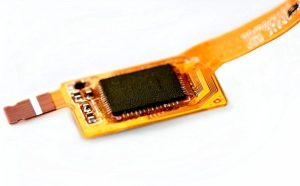
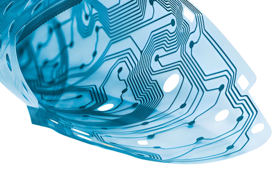
A Polyimide PCB is a printed circuit board that uses polyimide as its primary flexible dielectric substrate.
Polyimide, commonly abbreviated as PI, is a high-performance polymer known for its excellent thermal stability, flexibility, mechanical strength, and resistance to many chemicals.
Unlike a conventional rigid FR-4 PCB, a flexible polyimide PCB can be bent or folded to fit into limited spaces.
A typical polyimide flexible PCB consists of several functional layers, depending on the design:
- Polyimide dielectric substrate
- Copper conductor layer
- Coverlay or flexible solder mask
- Adhesive layers when required
- Stiffeners for component-support areas
- Surface finish
- Optional shielding layers
The copper layer provides the electrical pathways, while the polyimide substrate provides insulation and mechanical flexibility.
Because the substrate can tolerate repeated bending when properly designed, polyimide PCBs are particularly useful in applications where rigid boards would be difficult or impossible to install.
What Is Polyimide PCB Material?
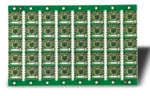
Polyimide PCB material is a high-performance polymer-based dielectric material used primarily in flexible circuit construction.
One of its defining characteristics is its ability to maintain useful mechanical and electrical properties across a relatively wide temperature range.
Depending on the specific polyimide formulation and construction, polyimide materials can support demanding thermal environments. This makes them particularly valuable for applications where the PCB may experience repeated thermal cycling, elevated operating temperatures, or thermal exposure during assembly.
Polyimide also provides excellent flexibility.
A properly designed Flexible PCB can be bent around corners, folded into compact spaces, or shaped to follow the contours of a product enclosure.
The material also provides good electrical insulation and chemical resistance, making it suitable for applications that require long-term reliability.
Another important advantage is its relatively low mass and thin construction. These characteristics help engineers reduce the size and weight of electronic assemblies.
However, material selection should always be based on the actual application. Different polyimide systems can have different dielectric, thermal, mechanical, dimensional-stability, and moisture-absorption characteristics.
Key Properties of Polyimide PCBs
Polyimide PCBs have a distinctive combination of physical, thermal, electrical, and mechanical properties.
High Thermal Stability
Polyimide is known for its excellent thermal stability compared with many conventional flexible-film materials.
Its high glass-transition or thermal-performance characteristics allow polyimide-based flexible circuits to withstand demanding assembly and operating conditions.
However, the exact maximum operating temperature depends on the specific polyimide formulation, copper construction, adhesive system, coverlay, and overall PCB design.
Therefore, engineers should always refer to the material manufacturer’s datasheet rather than assuming that every polyimide PCB has the same temperature rating.
Excellent Chemical Resistance
Polyimide contains a stable aromatic polymer structure that provides good resistance to many solvents, oils, and chemicals.
This characteristic is valuable in aerospace, automotive, industrial, and other environments where the PCB may be exposed to potentially aggressive substances.
High Mechanical Strength
Polyimide films offer good tensile strength and dimensional stability.
When properly constructed, they can withstand bending and mechanical movement while maintaining electrical continuity.
However, flexibility does not mean unlimited bending capability. Bend radius, copper type, copper thickness, layer construction, and dynamic versus static bending must all be considered during PCB Design.
Low and Controlled Thermal Expansion
Polyimide provides relatively stable dimensional characteristics over temperature changes.
This is important for flexible circuits because excessive dimensional change can affect layer registration, component placement, via alignment, and overall circuit reliability.
Excellent Flexibility
Flexibility is the defining feature of polyimide flexible circuits.
The material allows a PCB to conform to complex shapes and move with the mechanical structure of a product.
For dynamic applications, the copper type and bending geometry become particularly important. Rolled-annealed (RA) copper is often preferred for applications involving repeated flexing because of its mechanical fatigue characteristics.
Advantages of Polyimide PCBs
Polyimide PCBs provide several advantages over conventional rigid PCB materials.
Lightweight Construction
Polyimide flexible circuits can be manufactured with very thin dielectric layers and lightweight copper structures.
This can significantly reduce the weight and volume of an electronic assembly.
The advantage is particularly valuable in wearable electronics, aerospace equipment, portable medical devices, cameras, sensors, and compact consumer electronics.
Excellent Design Flexibility
A polyimide Flexible PCB can be folded, bent, or shaped around mechanical structures.
This allows designers to replace multiple rigid boards and wire connections with a single flexible circuit in some applications.
Flexible circuits can also reduce connector count and wiring complexity.
High Thermal Performance
Polyimide can maintain its mechanical and electrical properties under demanding thermal conditions.
This makes it suitable for applications exposed to elevated temperatures or repeated thermal cycling.
It is also widely used in high-temperature electronic assemblies where materials such as PET may not provide sufficient thermal performance.
Compact Three-Dimensional Integration
One of the most important benefits of flexible PCB technology is three-dimensional integration.
A flexible circuit can pass through narrow spaces, wrap around components, or connect multiple sections of a product.
This is particularly useful when conventional rigid PCBs would require additional connectors, cables, or mechanical space.
Reduced Assembly Complexity
Flexible circuits can integrate electrical connections into a single compact structure.
In some designs, this can reduce the number of connectors, wires, and separate PCB assemblies required.
Reducing interconnection points may also improve system reliability by eliminating potential connector or cable failure points.
Good Electrical Performance
Polyimide is an electrical insulating material with characteristics suitable for many high-density flexible circuit applications.
With appropriate stackup design, trace geometry, grounding, and material selection, polyimide flexible circuits can support high-speed and high-density electronic systems.
Limitations of Polyimide PCBs
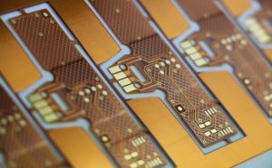
Although polyimide is one of the most important materials used in flexible circuits, it is not ideal for every application.
Higher Material and Manufacturing Cost
Polyimide flexible circuits generally cost more than conventional rigid FR-4 PCBs.
The additional cost may result from specialized materials, flexible-circuit fabrication processes, coverlay processing, tighter handling requirements, and specialized assembly procedures.
For highly cost-sensitive products, PET, PEN, or conventional rigid PCB materials may be considered when their thermal and mechanical characteristics are sufficient.
Moisture Absorption
Polyimide can absorb moisture from the environment.
Moisture can influence dimensional stability and may contribute to assembly-related reliability problems if the material is not properly handled.
For this reason, manufacturers should follow appropriate storage, drying, and pre-baking procedures based on the material supplier’s recommendations.
Moisture control is especially important before soldering or other high-temperature assembly processes.
More Difficult Manufacturing
Flexible PCBs require different handling techniques from rigid boards.
The thin substrate can be more susceptible to:
- Scratches
- Wrinkles
- Dimensional movement
- Layer misalignment
- Handling damage
- Copper fatigue
- Coverlay alignment problems
As a result, successful Polyimide PCB Manufacturing requires specialized processes and experienced production personnel.
Limited Mechanical Support
A flexible circuit is designed to bend, but its flexibility can also make component assembly more challenging.
Components may require stiffeners or localized rigid areas to provide mechanical support.
Therefore, engineers must consider both the flexible and rigid sections of the assembly during the initial design stage.
Polyimide PCB Manufacturing Process
The Polyimide PCB Manufacturing process is different from conventional rigid PCB fabrication because flexible materials require specialized handling and dimensional control.
1. Material Preparation
The first step is selecting the appropriate polyimide film, copper foil, adhesive system, coverlay, stiffener, and surface finish.
Material selection depends on:
- Required bend radius
- Dynamic or static flexing
- Operating temperature
- Electrical requirements
- Layer count
- Copper thickness
- Environmental conditions
- Assembly process
For high-reliability applications, material compatibility must be evaluated across the entire flexible PCB construction.
2. Lamination
When adhesive-based constructions are used, copper and dielectric layers can be laminated together under controlled temperature and pressure.
Temperature, pressure, heating rate, and curing conditions must be carefully controlled to prevent:
- Delamination
- Wrinkles
- Voids
- Excessive dimensional movement
- Adhesive-flow problems
For specialized adhesive-free flexible laminates, the manufacturing process may differ significantly from conventional adhesive-based constructions.
3. Drilling and Via Formation
Holes and vias are created using mechanical drilling, laser drilling, or other suitable processes.
The thin nature of flexible substrates requires careful control of drilling parameters.
After drilling, debris and residues must be removed to ensure reliable copper plating and interlayer connections.
4. Copper Plating
Copper is deposited onto the required conductive surfaces and inside drilled holes to create reliable electrical connections between layers.
Surface preparation is critical because good copper adhesion is essential for long-term flexing reliability.
5. Circuit Imaging and Etching
The required circuit pattern is transferred to the copper layer using photoimaging processes.
After exposure and development, unwanted copper is removed through controlled etching.
Trace geometry must be carefully controlled because conductor width and spacing directly affect electrical performance and mechanical flexibility.
6. Coverlay or Solder Mask Application
Flexible circuits commonly use polyimide coverlay rather than conventional rigid-board solder mask.
The coverlay protects copper traces from mechanical damage, moisture, contamination, and accidental electrical contact.
Openings are created in areas where soldering or electrical connections are required.
The coverlay design must also accommodate the required bending region and avoid creating unnecessary mechanical stress concentrations.
7. Surface Finish
Exposed copper pads may receive a suitable surface finish such as ENIG or another finish selected according to the assembly and reliability requirements.
The surface finish protects copper from oxidation and supports solderability.
8. Stiffener Application
Stiffeners may be added to selected areas of a flexible PCB.
For example, a stiffener can reinforce connector fingers, component-mounting regions, or soldering areas.
The stiffener does not necessarily make the entire circuit rigid; instead, it provides localized mechanical support where required.
9. Inspection and Testing
Quality control is particularly important for flexible circuits.
Depending on the application, testing may include:
- Automated optical inspection (AOI)
- Electrical continuity testing
- Short-circuit testing
- Dimensional inspection
- Microsection analysis
- Copper-thickness measurement
- Peel-strength testing
- Solderability testing
- Flex-cycle testing
- Visual inspection
For demanding applications, Kingda can establish inspection and testing procedures according to the project’s technical specifications.
Challenges in Polyimide PCB Manufacturing
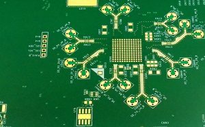
Polyimide PCB production presents several challenges that require careful process control.
Delamination
Delamination occurs when different layers within a flexible PCB lose their adhesion.
Potential contributing factors include:
- Moisture
- Excessive thermal stress
- Poor lamination parameters
- Incompatible materials
- Repeated mechanical bending
- Contamination
- Inadequate surface preparation
Proper material selection and process control are essential to minimize this risk.
Layer Registration
Thin flexible materials can experience dimensional changes during processing.
Temperature, moisture, mechanical tension, and manufacturing processes can cause the substrate to expand, contract, or distort.
This makes layer-to-layer registration more challenging than with many rigid PCB constructions.
High-density flexible circuits therefore require accurate imaging, registration, and process control.
Copper Fatigue
Repeated bending places mechanical stress on copper conductors.
Over time, repeated flexing can cause conductor fatigue or cracking.
For dynamic-flex applications, engineers should carefully evaluate:
- Copper type
- Copper thickness
- Bend radius
- Number of flex cycles
- Flexing direction
- Neutral-axis position
- Stiffener location
RA copper is commonly considered for demanding dynamic-flex applications because of its favorable fatigue characteristics.
How to Overcome Flexible PCB Manufacturing Challenges
Experienced manufacturers can reduce production risks by controlling materials, environmental conditions, and manufacturing parameters.
Recommended practices include:
- Select high-quality polyimide materials with verified specifications.
- Store flexible materials under controlled environmental conditions.
- Follow supplier-recommended drying and pre-baking procedures before high-temperature assembly.
- Design according to applicable IPC flexible-circuit guidelines.
- Use appropriate bend radii and avoid placing vias or other stress-sensitive features directly in high-flex areas.
- Avoid sharp conductor corners and abrupt changes in trace geometry in bending regions.
- Use appropriate stiffeners where components or connectors require additional mechanical support.
- Control lamination, imaging, drilling, plating, and coverlay processes carefully.
- Perform appropriate electrical, dimensional, and mechanical testing before shipment.
The best results are achieved when PCB Design and manufacturing engineering are considered together rather than treating manufacturing as a separate final step.
Applications of Polyimide PCBs
Polyimide PCBs are used across industries where flexibility, compactness, thermal stability, and reliability are important.
Medical Electronics
Flexible polyimide circuits are used in various medical and healthcare electronics.
Potential applications include:
- Wearable sensors
- Patient-monitoring devices
- Medical instrumentation
- Compact diagnostic equipment
- Catheter-related electronics
- Flexible sensor assemblies
Their thin and conformable construction can be valuable where electronics must fit into compact or curved structures.
Consumer Electronics
Modern consumer electronics increasingly require compact and lightweight interconnections.
Flexible circuits can be used in:
- Smartphones
- Tablets
- Wearable devices
- Cameras
- Displays
- Portable electronics
- Compact sensors
A flexible circuit can connect components across different sections of a compact product without requiring bulky cable assemblies.
Aerospace and Defense
Aerospace electronics often require lightweight materials capable of operating under demanding environmental conditions.
Polyimide flexible circuits can be used in avionics, sensors, instrumentation, communication systems, and other aerospace electronic assemblies.
Weight reduction can be particularly valuable in airborne systems.
Automotive Electronics
Modern vehicles contain a growing number of sensors, displays, cameras, control modules, and electronic interfaces.
Flexible PCBs can be used in:
- Instrument clusters
- Camera modules
- Lighting systems
- Infotainment systems
- Sensors
- Steering-wheel electronics
- Battery and power-management systems
Polyimide is particularly useful when the circuit must fit into a confined or moving space.
Industrial Electronics
Industrial equipment often requires flexible interconnections between moving or mechanically separated components.
Applications may include robotics, automation systems, sensors, instrumentation, and industrial control equipment.
Polyimide (PI) PCB vs. PEN PCB vs. PET PCB
PI, PEN, and PET are three important polymer materials used in flexible electronics.
However, they have different thermal, mechanical, dimensional, and cost characteristics.
| Property | Polyimide (PI) | PEN | PET |
|---|---|---|---|
| Thermal capability | Highest among the three in typical flexible PCB applications | Intermediate | Generally lower |
| Flexibility | Excellent | Good | Good |
| Mechanical durability | Excellent | Good | Moderate to good |
| Chemical resistance | Excellent | Good | Moderate |
| Dimensional stability | Excellent | Good | Moderate |
| Relative cost | High | Medium | Low |
| Typical applications | High-reliability flexible circuits, aerospace, automotive, medical, industrial | Flexible electronics requiring a balance of performance and cost | Cost-sensitive flexible electronics and printed electronics |
| High-temperature assembly suitability | Excellent, depending on construction | More limited than PI | Generally more limited than PI |
The exact temperature limits vary by resin formulation, film grade, adhesive system, and PCB construction, so manufacturers should always use the material supplier’s datasheet rather than applying a single temperature value to all PI, PEN, or PET materials.
Which Substrate Is Right for Your Flexible PCB?
Choosing the right Flexible PCB substrate requires balancing mechanical, thermal, electrical, environmental, and economic requirements.
1. Evaluate Mechanical Flexibility
Determine whether the circuit will remain stationary after installation or repeatedly flex during operation.
Static-bend and dynamic-flex applications can require significantly different material and copper constructions.
2. Consider Operating Temperature
For high-temperature applications, polyimide generally provides a wider performance margin than PET or many lower-cost flexible substrates.
The complete PCB construction should be evaluated rather than considering the film alone.
3. Evaluate Electrical Requirements
For high-speed or RF applications, dielectric constant, dissipation factor, conductor geometry, shielding, and stackup must all be considered.
The selected material should be evaluated at the actual operating frequency.
4. Consider Production Cost
PET and PEN can provide lower-cost options for applications where extreme thermal performance is not required.
Polyimide generally involves a higher material and manufacturing cost, but it can provide additional performance for demanding applications.
5. Consider Environmental Requirements
Evaluate exposure to:
- Heat
- Humidity
- Chemicals
- Vibration
- Mechanical movement
- Thermal cycling
- UV exposure
- Contamination
The substrate and complete PCB construction should be selected according to the actual operating environment.
6. Consider Regulatory Requirements
Depending on the target market, the PCB may need to comply with applicable environmental and industry requirements.
RoHS compliance may be required for products sold in relevant markets, while automotive, medical, aerospace, and other industries may require additional standards and qualification procedures.
How to Choose a Polyimide PCB Manufacturer
Choosing an experienced Polyimide PCB Manufacturer is important because flexible PCB production requires specialized materials, processes, and handling procedures.
Material and Process Capability
First, verify whether the manufacturer can process the required polyimide laminate, copper foil, coverlay, stiffeners, and surface finish.
Flexible PCB Experience
Ask about the manufacturer’s experience with both static-flex and dynamic-flex applications.
Dynamic applications require particular attention to copper fatigue, bend radius, layer construction, and mechanical reliability.
Manufacturing and Inspection Capability
A capable manufacturer should have appropriate equipment and inspection procedures for:
- Fine-line fabrication
- Flexible material handling
- Precision drilling
- Copper plating
- Coverlay processing
- AOI
- Electrical testing
- Dimensional inspection
- Flex testing
Engineering Support
A reliable manufacturing partner should be able to review the design before production and identify potential problems related to bend radius, component placement, coverlay openings, stiffeners, vias, copper geometry, and manufacturing tolerances.
Quality Management
Depending on the target application, customers should evaluate applicable ISO certifications, IPC requirements, and industry-specific qualifications.
Kingda can support customers with flexible PCB manufacturing requirements and provide engineering coordination from design review through fabrication and inspection.
Polyimide PCB Design Best Practices
Successful Polyimide PCB Design requires more than simply replacing an FR-4 substrate with polyimide.
Avoid Sharp Corners in Flexible Areas
Trace paths in bending regions should generally avoid sharp corners.
Smooth routing can reduce mechanical stress concentrations and improve flexing reliability.
Keep Vias Away from High-Flex Areas
Vias create localized mechanical structures that can become stress concentrations.
Whenever possible, sensitive via structures should be kept away from regions subjected to repeated bending.
Use Appropriate Bend Radius
The minimum bend radius depends on the number of layers, copper thickness, material construction, and whether the application involves static or dynamic bending.
Designers should follow the PCB manufacturer’s recommended bend-radius limits.
Place Components in Rigidized Areas
Components can create mechanical stress and require a stable mounting surface.
Stiffeners or rigidized regions may therefore be used beneath component-mounting areas.
Optimize Copper Geometry
Copper thickness and conductor geometry affect both electrical performance and mechanical reliability.
For repeated bending, the conductor construction should be selected specifically for flexing performance rather than simply maximizing copper thickness.
Conclusion
The Polyimide PCB has become an important technology for modern flexible electronics because it combines flexibility, thermal stability, mechanical strength, chemical resistance, and lightweight construction.
Compared with conventional rigid PCB materials, polyimide allows circuits to bend and conform to complex three-dimensional structures. This makes it particularly useful for medical devices, wearable electronics, automotive systems, aerospace equipment, industrial automation, cameras, displays, and other compact electronic products.
However, polyimide is not automatically the right material for every flexible circuit. Higher cost, moisture absorption, specialized manufacturing requirements, and mechanical design considerations must all be evaluated.
Successful Polyimide PCB Manufacturing depends on appropriate material selection, controlled lamination, accurate imaging and etching, reliable copper plating, proper coverlay application, suitable stiffeners, environmental control, and comprehensive testing.
At the design stage, engineers should also consider bend radius, copper type, flex-cycle requirements, via placement, component location, thermal conditions, and manufacturing tolerances.
As electronics continue to become smaller, lighter, and more integrated, flexible circuit technology will remain an important part of advanced electronic product development. Working with an experienced manufacturer such as Kingda can help engineers translate flexible PCB concepts into manufacturable, reliable, and application-specific circuit boards.