


Engineering Context
Metal-core printed circuit boards (MCPCBs) have become a critical platform for modern electronics where thermal management, mechanical stability, and signal integrity must be balanced. Among them, aluminum-based PCBs and copper-based PCBs are the two most widely deployed solutions. Although they share a similar stack concept—a conductive circuit layer, a thermally conductive dielectric, and a metal substrate—their material properties, dielectric behavior, RF performance, and reliability differ significantly. This article provides an engineer-oriented comparison of metal-core PCBs, aluminum-based PCBs, and copper-based PCBs, focusing on thermal physics, material science, stackup design, RF/mmWave behavior, and real-world industrial applications.
Core Engineering Challenges
High-power-density electronics face three fundamental challenges: heat dissipation, electrical insulation, and long-term reliability. As power devices, RF front ends, and high-frequency modules shrink in size, localized heat flux increases dramatically. Traditional FR-4 substrates struggle to remove heat efficiently, leading to phase instability, insertion loss drift, and premature component failure.
Metal-core PCBs address these issues by integrating a metal substrate that functions as a heat spreader. However, the choice between aluminum-based PCBs and copper-based PCBs introduces trade-offs in cost, manufacturability, dielectric stress, EMI behavior, and RF PCB performance. Engineers must also consider mechanical stiffness, coefficient of thermal expansion (CTE) mismatch, and environmental durability.
Material Science & Dielectric Performance
Metal-core PCBs are defined by their substrate rather than their circuit layer. The most common variants include aluminum-based PCBs and copper-based PCBs, both classified as MCPCBs.
Aluminum-Based PCB Aluminum-based PCBs use an aluminum substrate (typically 1.0–3.0 mm thick) bonded to a thermally conductive dielectric layer and copper circuitry. Aluminum offers moderate thermal conductivity, low density, and excellent corrosion resistance. The dielectric layer—often ceramic-filled epoxy or polymer—provides electrical insulation while enabling vertical heat transfer.
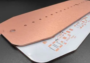
Copper-Based PCB Copper-based PCBs replace the aluminum substrate with copper. Copper exhibits significantly higher thermal conductivity and electrical conductivity, resulting in superior heat spreading and phase stability under high power and high frequency operation. However, copper substrates increase weight, cost, and machining complexity.
Material Parameter Comparison
| Parameter | Aluminum-Based PCB | Copper-Based PCB |
|---|---|---|
| Thermal Conductivity (W/m·K) | ~200–230 | ~380–400 |
| Density (g/cm³) | 2.7 | 8.96 |
| Electrical Conductivity | Moderate | Very High |
| Cost Level | Low–Medium | High |
| Typical Use Case | Power LEDs, industrial control | RF, mmWave, high-power modules |
The dielectric layer thickness typically ranges from 50–200 μm and plays a decisive role in breakdown voltage, EMI suppression, and insertion loss. For RF PCB designs, low-loss dielectrics with stable Dk over temperature are essential.
GOPCBA Case Study — Automotive Radar PCB
Industry Scenario: Automotive millimeter-wave radar module (77 GHz)
Customer Requirements
- High thermal conductivity for power amplifier stages
- Phase stability across -40°C to +125°C
- Low insertion loss at mmWave frequencies
- Long-term reliability under vibration and humidity
Engineering Challenges Aluminum-based PCBs provided adequate heat dissipation but exhibited phase drift and increased insertion loss at elevated temperatures. Standard FR-4 was eliminated due to excessive dielectric loss.
GOPCBA Solution KKPCB selected a copper-based MCPCB with a low-loss ceramic-filled dielectric optimized for RF PCB applications. A symmetrical stackup minimized warpage and ensured consistent impedance control.
Measured Results
| Test Item | Requirement | Measured Result |
| Thermal Resistance | ≤1.5 °C/W | 1.1 °C/W |
| Insertion Loss @77 GHz | ≤2.5 dB | 2.1 dB |
| Phase Stability | ±2° | ±1.2° |
| EMI Compliance | CISPR 25 | Pass |
Stackup Design & RF Implementation
A typical MCPCB stackup consists of:
| Layer Order | Description | Function |
| Top Copper Layer | 1–3 oz Cu | Signal / Power Routing |
| Dielectric Layer | Ceramic-filled polymer | Electrical insulation, heat transfer |
| Metal Core | Aluminum or Copper | Heat spreading, mechanical support |
For RF and mmWave designs, symmetry in the stackup is critical. Copper-based PCBs offer superior impedance stability due to lower CTE mismatch between copper foil and copper substrate. Aluminum-based PCBs are more susceptible to slight mechanical deformation, which can affect RF phase matching.
Simulation tools such as HFSS and ADS are commonly used to model insertion loss, EMI coupling, and impedance profiles. TDR measurements validate controlled impedance, while thermal FEM simulations predict junction temperature under full load.
Environmental & Reliability Validation
Metal-core PCBs must pass stringent reliability testing, especially in automotive, aerospace, and industrial sensor applications.
| Test Type | Condition | Result |
| Thermal Cycling | -40°C ↔ +125°C, 1000 cycles | Pass |
| Humidity Storage | 85°C / 85% RH, 1000 hrs | Pass |
| Vibration | Automotive profile | Pass |
| Solder Reflow | 260°C, 6 cycles | No delamination |
Copper-based PCBs generally demonstrate better long-term reliability under thermal cycling due to their higher mechanical strength and thermal conductivity. Aluminum-based PCBs remain an excellent choice where cost, weight, and moderate thermal performance are prioritized.
Engineering Summary & Contact
Metal-core PCBs provide a robust solution for heat-intensive electronics. Aluminum-based PCBs offer an optimal balance of cost, weight, and thermal performance for lighting, industrial control, and power conversion. Copper-based PCBs deliver unmatched thermal conductivity, RF stability, and reliability for high-frequency, mmWave, and mission-critical systems.
Selecting the correct MCPCB material requires a holistic evaluation of thermal load, RF performance, environmental conditions, and manufacturing constraints. GOPCBA supports custom aluminum-based PCBs and copper-based PCBs with advanced simulation, prototyping, and validation services.
For engineering consultation, stackup optimization, or RF PCB manufacturing support, contactGOPCBA engineering team.