


Engineering Context / Abstract
Through-hole PCB assembly (THT assembly) remains a critical manufacturing technology for electronics that demand superior mechanical strength, high current capability, and long-term reliability. While surface-mount technology dominates high-density consumer electronics, through-hole PCB assembly continues to be indispensable in industrial controls, medical equipment, power electronics, automotive modules, aerospace systems, and harsh-environment applications.
In through-hole PCB assembly, component leads are inserted into plated through-holes and soldered to copper pads on one or both sides of the PCB. This creates robust metallurgical bonds that offer excellent resistance to vibration, thermal cycling, and mechanical stress. This article examines through-hole PCB assembly from an engineering perspective, focusing on material science, stackup considerations, soldering processes, and reliability validation aligned with high-reliability system requirements.

Core Engineering Challenges
Through-hole PCB assembly introduces engineering challenges distinct from those of SMT assembly, particularly when applied to mission-critical electronics.
Mechanical stress and vibration resistance are primary considerations. Through-hole components are often used in environments subject to shock, vibration, and mechanical loading. PCB materials, copper plating quality, and solder joint geometry must work together to prevent fatigue and cracking over long service lifetimes.
Thermal stress management is another challenge. Many through-hole components, such as transformers, power connectors, and large capacitors, dissipate significant heat. The PCB stackup must support effective heat spreading without inducing excessive CTE mismatch between copper, laminate, and component leads.
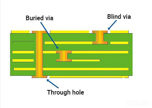
Hole integrity and plating reliability directly affect assembly quality. Inadequate via wall thickness or poor adhesion can result in barrel cracking, pad lifting, or intermittent electrical failures after thermal cycling.
Finally, process control and repeatability are critical. Wave soldering and selective soldering processes must be tightly controlled to ensure complete hole fill, minimal voiding, and consistent solder fillet formation across high-mix production.
Material Science & Dielectric Performance
Material selection plays a foundational role in through-hole PCB assembly, influencing mechanical robustness, thermal stability, and long-term electrical reliability.
High-Tg FR-4 materials are commonly used due to their balanced cost, mechanical strength, and electrical performance. For power and industrial applications, thicker cores and heavier copper weights are often selected to support higher current densities and improved thermal performance.
Typical Material Parameters for Through-Hole PCB Assembly
| Parameter | Typical Value | Engineering Impact |
|---|---|---|
| Dielectric Constant (Dk) | 3.8 – 4.5 | Stable signal behavior |
| Glass Transition (Tg) | ≥170 °C | Thermal endurance |
| Copper Thickness | 1–3 oz | Current capacity |
| Via Wall Thickness | ≥25 µm | Mechanical reliability |
| Z-axis CTE | ≤70 ppm/°C | Barrel crack resistance |
Low ionic contamination and controlled resin systems are essential to prevent electrochemical migration, particularly in humid or high-voltage environments. In mixed-technology designs, localized RF PCB materials may be used alongside standard laminates to maintain signal integrity without compromising mechanical strength.
GOPCBA Case Study — Industrial Control PCB
Customer Background
An industrial automation manufacturer required a through-hole PCB assembly solution for a motor control and power distribution module. The PCB integrated high-current connectors, relays, transformers, and control circuitry, designed to operate continuously in a factory environment with elevated temperatures and mechanical vibration.
Engineering Problems
-
Solder joint cracking under vibration testing
-
Incomplete hole fill on thick copper boards
-
Thermal stress causing pad lifting near power components
-
Variability in assembly quality across production batches
GOPCBA Solution
GOPCBA implemented a reliability-driven through-hole PCB assembly process. Key improvements included optimized hole-to-lead diameter ratios, enhanced via plating thickness, and controlled wave soldering parameters tailored for heavy copper designs.
Selective soldering was applied to thermally sensitive areas, ensuring consistent solder fillets while protecting nearby components. Process monitoring and X-ray inspection were used to validate solder joint integrity.
Measured Performance Results
| Test Item | Requirement | Measured Result |
|---|---|---|
| Hole Fill Rate | ≥95% | 99.2% |
| Solder Joint Pull Strength | ≥30 N | 46 N |
| Thermal Cycling | 500 cycles | No cracks |
| Assembly Yield | ≥98% | 99.4% |
The optimized through-hole PCB assembly met both mechanical and electrical reliability requirements for industrial deployment.
Stackup Design & RF Implementation
Although through-hole PCB assembly is often associated with power and low-frequency applications, stackup design remains critical for signal integrity, EMI control, and mechanical stability.
Example Through-Hole PCB Stackup
| Layer | Function | Material |
|---|---|---|
| L1 | Components / Signal | High-Tg FR-4 |
| L2 | Solid Ground Plane | Copper |
| L3 | Power Plane | Copper |
| L4 | Control Signals | High-Tg FR-4 |
| L5 | Ground Plane | Copper |
| L6 | Bottom Components | High-Tg FR-4 |
This stackup provides short return paths for signals, effective EMI suppression, and balanced copper distribution to reduce warpage during soldering. For designs integrating RF or high-speed interfaces, impedance-controlled traces are routed on dedicated layers with continuous reference planes.
Simulation using TDR analysis validated impedance consistency, while power integrity simulations confirmed stable voltage delivery under high current loads. Thermal FEM analysis supported heat spreading optimization around large through-hole components.
Environmental & Reliability Validation
Through-hole PCB assemblies intended for high-reliability applications must undergo comprehensive environmental and mechanical validation.
Reliability Test Summary
| Test Type | Condition | Result |
|---|---|---|
| Thermal Cycling | −40 °C ↔ 125 °C, 500 cycles | Pass |
| High-Temp Operating Life | 105 °C, 1000 hrs | Pass |
| Humidity Exposure | 85 °C / 85% RH | Pass |
| Vibration | Industrial standard | Pass |
| Mechanical Shock | 50 g | Pass |
| Solder Reflow Simulation | Multiple thermal profiles | No defects |
Wave solder and selective solder joints demonstrated strong resistance to fatigue and maintained electrical continuity throughout testing. Cross-section analysis confirmed uniform solder wetting and adequate barrel fill, supporting long-term reliability.
Engineering Summary & Contact
Through-hole PCB assembly remains a cornerstone technology for electronics requiring exceptional mechanical strength, high current handling, and long-term reliability. By combining appropriate material selection, optimized stackup design, controlled soldering processes, and rigorous validation, through-hole PCB assemblies can meet the demanding requirements of industrial, medical, automotive, and aerospace systems.
An engineering-driven approach to through-hole PCB assembly ensures consistent quality, predictable performance, and extended service life under harsh operating conditio. GOPCBAns provides comprehensive through-hole PCB assembly services, including process optimization, reliability testing, and mixed-technology integration to support high-reliability electronic products across multiple industries.