
High Volume PCB Assembly: Mass PCBA Manufacturing Checks
High volume PCB assembly turns a proven design into thousands of boards that must behave the same way. The design is fixed, the demand is predictable, and the factory now carries the risk. Small process drifts that a prototype run would hide become large yield losses once the line runs for weeks. This article explains what changes at volume, which controls matter most, and what a buyer should verify before releasing a mass PCBA order.
Volume changes the economics of every decision. Setup time spreads across more boards, so tooling and engineering review cost less per unit. Material purchases grow, which improves component availability and price stability. Inspection becomes a sampling and data problem rather than a manual task. The same discipline applies to high-volume PCB assembly, where a small process drift turns into a large yield loss. Planning that reality before the first article saves rework later in the run.
What Volume Really Means
There is no universal quantity that defines high volume. The threshold depends on board complexity, component count, test time, and the production cycle the customer needs. A dense board with many fine-pitch parts may reach volume at a few thousand units. A simple board may need tens of thousands before automation pays off. Buyers should describe demand honestly and let the factory match the line and the process to it.
Volume also changes how the factory plans capacity. A recurring order needs reserved line time, qualified material alternates, and a stable stencil and profile library. One large order needs a burst plan and a clear shipping schedule. Both cases require the same thing: a documented process that does not depend on one operator or one machine. Ask how the supplier separates repeat orders from one-time builds.
Stackup Choices
At volume, the bare board and the assembly must be designed as one system. Layer count, copper weight, and surface finish affect solderability, warpage, and reflow behavior across the whole panel. A finish that works on a prototype may create issues when thousands of boards pass through the same oven. Review the drawing, the process sheet, and the inspection plan before release, and confirm that fabrication and assembly agree on the same specification.
Panel design deserves early attention. Panel size, rail width, fiducial placement, and breakaway method decide how well the printer and the placement machine perform. A panel that is awkward to support will flex and cause placement errors. Tooling holes and clearances should be agreed before fabrication starts. Buyers should ask for the panel drawing and check that the assembly team reviewed it, not only the fabrication team.
Solder Paste and Printing
The printer sets the solder volume for every joint on the board. Stencil thickness, aperture design, and squeegee pressure must be tuned for the component mix, then held within a window. Paste age, room temperature, and humidity all shift viscosity. A batch that sits too long prints differently from a fresh one. Factories that control paste life and record the lot number remove a common source of variation before it reaches the oven.
Print inspection gives the first real feedback of the run. Measuring paste height and volume after printing catches stencil and support problems while correction is still cheap. That data also feeds the trend line that reveals drift over days. Ask how print results are recorded and who reviews them. A factory that prints well but does not measure is relying on luck, and luck does not survive a long production run.
Placement and Reflow Control
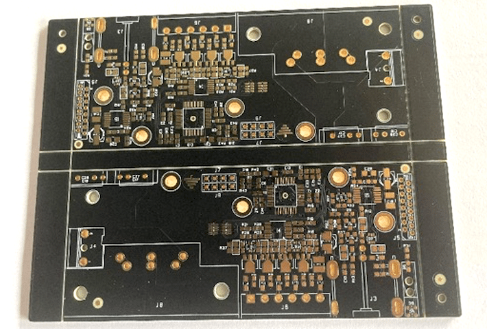
Automated placement handles speed and repeatability, but it still needs correct programs, verified feeders, and calibrated nozzles. Component packaging matters at volume. Reels, trays, and sticks must suit the machine, and moisture-sensitive parts need proper storage and baking records. A wrong reel or a dry-pack violation can spoil a whole lot. Incoming inspection should check part numbers, quantities, and packaging against the approved BOM before anything reaches the line.
Reflow forms the joint, and the profile must match the board, the paste, and the thermal mass of the assembly. Large copper areas and heavy connectors pull heat away, so a single profile may not fit every panel position. Thermocouple checks on real boards confirm the profile before release. Every change in materials, stencils, or profiles feeds back into the process, so the factory should log each revision and retest when something moves.
Through-Hole and Mixed Builds
Many volume products still need through-hole parts for connectors, power devices, or mechanical strength. Wave soldering, selective soldering, and pin-in-paste reflow each suit different mixes. The choice affects hole size, mask clearance, and the order of operations. A design that assumes one method may need changes when the factory selects another. Discuss the assembly sequence early, and confirm that the fabrication drawing supports the soldering method chosen.
Mixed technology builds add handling steps, and each step is a chance for damage. Boards may travel between SMT and through-hole lines, and masking, insertion, and cleaning all add touch points. Clear work instructions and defined hold points keep the sequence consistent. Buyers should ask how the factory protects sensitive parts during the second pass and how it verifies that no component was disturbed.
Inspection and Test Coverage
Inspection at volume is a data program, not a final gate. Solder paste inspection, optical inspection, and X-ray each cover different defect types. Optical inspection finds placement and polarity errors quickly. X-ray reveals hidden joints under packages and connectors. Electrical test confirms connectivity and value, while functional test proves the board works as a system. The right mix depends on the product and the cost of a field failure.
Test coverage should be agreed before production, not added after defects appear. First article inspection confirms the setup, and the approved unit becomes the reference for the run. A structured PCBA testing plan links each test to a failure mode and records the result against the lot. When a defect appears, the record shows whether the cause was paste, placement, soldering, or a component, and that closed loop pushes defect rates down over time.
Supplier and Documentation Review
Before releasing a large order, verify how the supplier manages change. Ask how it handles engineering questions, material substitutions, and process revisions. Confirm that incoming inspection, paste control, profile logging, and test records are kept with the lot. A factory with a working quality management system can show these records on request. A factory without them will describe good practice but struggle to prove it happened on your boards.

Traceability matters most months later, when a field return arrives. The batch record should show which program ran, which material lots were used, and what inspection found. That record is the fastest route to a cause and the proof that a fix reached the next batch. Buyers should treat documentation as part of the product, not as paperwork, and should ask to see a sample record during the audit.
Prototype to Volume Transition
The move from prototype to volume is where many programs lose time. A design that passed a small build may still have pad, tolerance, or panel issues that only appear at speed. A rapid PCBA prototyping stage lets the team test the process before committing to a large order. The pilot run should use the same stencil design, the same profile family, and the same test approach as the volume build.
Early engineering review catches most of these problems. Design for manufacturing checks pad geometry, spacing, and component orientation. Design for assembly checks clearance for tools and handling. Fixing these points before tooling costs a message. Fixing them after thousands of boards are built costs a rework line and a delayed launch. Buyers should ask for the review report and confirm that each finding was closed before release.
Cost and Capacity Planning
Unit cost falls as volume grows, but only when the process is stable. Larger material purchases, better equipment use, and fewer setups all reduce the cost per board. Scrap and rework, however, can erase those gains quickly. A line that runs fast but produces defects is more expensive than a slower line that holds its window. Buyers should compare total cost, including test time, yield, and delivery risk, rather than the quoted price alone.
Capacity planning protects the schedule. Ask how the factory reserves line time for repeat orders and how it handles demand spikes. Confirm that component sourcing has approved alternates for long-lead parts. A supplier that reviews the BOM for availability before quoting will flag risks early. The same care applies to SMT PCB assembly lines that serve many customers, where shared capacity must be booked rather than assumed.
The practical takeaway is simple. Treat the first article as a contract between design and production. Agree the panel, the stencil, the profile, the test plan, and the record format before the run starts. Then verify that the factory measures what it promised and keeps the data with the lot. That preparation costs little at the start and protects the whole order when the line is running at full speed.