Multilayer PCB Manufacturing Process: Complete Step-by-Step Guide
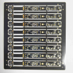
Multilayer PCB manufacturing is a sequential fabrication process that transforms copper-clad laminates into complex circuit boards with three or more conductive layers. The process begins with design data preparation (CAM) and inner layer imaging, followed by layer stack-up and lamination under heat and pressure, then drilling, plated-through-hole (PTH) copper plating, outer layer imaging, solder mask application, surface finishing, routing, and electrical testing[reference:0]. Each additional layer pair compounds the complexity of registration accuracy, drilling precision, and thermal management[reference:1]. This guide walks through every critical stage—from 4-layer designs through 40+ layer constructions—with real-world process parameters, IPC standards, and quality control checkpoints that ensure first-pass yield in high-reliability applications.
What Is a Multilayer PCB?
A multilayer PCB is a printed circuit board with three or more copper conductive layers separated by insulating dielectric materials (cores and prepregs) and laminated into a single solid structure[reference:2]. Unlike single-sided or double-sided boards, multilayer PCBs enable higher wiring density in compact footprints, dedicated power and ground planes for improved electromagnetic interference (EMI) performance, and superior signal integrity for high-speed digital and RF applications[reference:3].
Multilayer PCBs are fundamental to modern electronics—from smartphones and medical devices to aerospace systems and automotive electronics[reference:4]. Layer counts typically range from 4 to 40+ layers, with each additional layer pair increasing manufacturing complexity in material handling, alignment precision, drilling accuracy, and thermal management[reference:5].
Key characteristics: high circuit density, support for complex routing, improved power distribution, dedicated ground planes for noise reduction, and reliable performance in demanding environments[reference:6].
For a deeper understanding of PCB design considerations, explore our PCB design and layout services.
Stage 1: Design Data Preparation (CAM)
Before any physical manufacturing begins, the CAM (Computer-Aided Manufacturing) department processes the customer’s Gerber or ODB++ design files[reference:7]. This critical stage includes four essential steps that directly determine manufacturability and yield.
Design Rule Check (DRC)
DRC verifies that the design meets the manufacturer’s capabilities—minimum trace width and spacing, annular ring sizes, and drill-to-copper clearances[reference:8]. For high-layer-count boards, minimum trace/space of 3/3 mil (75/75 µm) with contact printing or 2/2 mil (50/50 µm) with Laser Direct Imaging (LDI) is typical[reference:9].
Panelization
Individual boards are arranged on a manufacturing panel—typically 18″ × 24″ or 21″ × 24″—with tooling borders, fiducial marks, registration targets, and test coupons[reference:10]. Panelization optimizes material utilization and production efficiency.
Scaling Compensation
X and Y scaling factors are applied to inner layer artwork to compensate for material movement during lamination. Typical scaling: 0.5–3.0 mils per 10 inches, dependent on material type, layer position, and copper distribution[reference:11]. This compensation is critical for maintaining layer-to-layer registration accuracy.
Drill File Optimization
Drill files are merged, tooling holes are added, and the drill sequence is optimized to minimize tool changes and reduce manufacturing time[reference:12].
Stage 2: Inner Layer Fabrication
Each inner layer begins as a copper-clad laminate (core)—a cured sheet of resin/fiberglass composite with copper foil bonded to both sides[reference:13]. The inner layer fabrication process transforms these raw cores into patterned circuit layers.
Surface Preparation
The copper surface is chemically cleaned and micro-roughened (using pumice scrub or chemical micro-etch) to promote photoresist adhesion. Target surface roughness: Ra 0.3–0.5 µm[reference:14].
Photoresist Lamination
Dry film photoresist—typically 25–50 µm thick—is laminated onto both sides of the core using hot rollers at 100–110°C and 3–5 bar pressure[reference:15].
Exposure (Imaging)
The circuit pattern is transferred to the photoresist using either contact printing (phototool film) achieving ≥3/3 mil resolution, or Laser Direct Imaging (LDI) achieving ≥2/2 mil resolution with superior accuracy and repeatability[reference:16]. LDI is the standard for high-layer-count boards where registration precision is paramount[reference:17].
Development and Etching
The exposed panel is developed in a sodium carbonate solution (1–1.5% Na₂CO₃), removing unexposed photoresist[reference:18]. Unprotected copper is then etched away, leaving the circuit traces. The remaining resist is stripped, and the inner layers undergo Automated Optical Inspection (AOI) to detect shorts, opens, and defects[reference:19].
Learn more about our PCB manufacturing capabilities and quality standards.
Stage 3: Lamination and Layer Stack-Up
Lamination bonds the inner layers, prepregs, and copper foils into a solid, integrated multilayer panel[reference:20]. This is one of the most critical stages in multilayer PCB manufacturing, where multiple layers are permanently fused under heat and pressure.
Oxide Treatment (Brown/Black Oxide)
Copper surfaces are treated with brown oxide or black oxide to roughen the surface and enhance resin bonding[reference:21][reference:22]. This chemical treatment creates a micro-rough copper surface that improves adhesion between the copper and the prepreg resin.
Pre-Stacking and Lay-Up
Multiple inner layers are precisely aligned with prepreg sheets (pre-impregnated resin) and temporarily fixed with rivets to prevent misalignment[reference:23]. Copper foils are placed on the outer sides, forming the outermost layers[reference:24]. Alignment accuracy is critical—even slight misregistration can cause open circuits when drilled holes fail to connect to internal pads[reference:25].
Lamination Press
The entire stack is placed in a lamination press under heat and pressure. Typical lamination parameters for FR-4 materials: 180–200°C at 300–500 PSI[reference:26]. Under these conditions, the resin in the prepreg melts, flows, and bonds everything together[reference:27]. Kraft paper and steel press plates ensure uniform pressure distribution and panel flatness[reference:28].
For projects requiring high-reliability multilayer boards, explore our turnkey PCB assembly services.
Stage 4: Drilling and Plated Through-Holes (PTH)
Once the laminate stack is formed, holes are drilled to create electrical connections between layers[reference:29].
X-Ray Alignment
Before drilling, an X-ray procedure locates internal reference points to precisely align holes with inner layer pads[reference:30]. This ensures that drilled holes will correctly intersect the target pads on each inner layer.
Drilling
High-speed mechanical drills create through-holes, blind vias, and buried vias[reference:31]. For HDI (High Density Interconnect) multilayer boards, laser drilling is used for microvias[reference:32]. As layer counts increase and hole diameters decrease, laser drilling becomes essential for achieving the required aspect ratios[reference:33].
Desmear and Activation
After drilling, chemical processes remove resin smear from hole walls (desmear) and activate the surfaces for copper deposition[reference:34].
Copper Plating (PTH)
A thin layer of copper is deposited on the hole walls and surfaces through electroless copper deposition, followed by electrolytic copper plating to build up the required copper thickness[reference:35][reference:36]. This creates conductive pathways (plated through-holes) connecting all layers.
Stage 5: Outer Layer Imaging and Etching
The outer copper layers (top and bottom) are patterned using the same photolithography process as inner layers—photoresist lamination, exposure, development, and etching[reference:37]. Additional copper plating may be applied to circuit areas before the photoresist is stripped, building up trace thickness for current-carrying capacity[reference:38].
Outer layer imaging requires precise alignment with the already-laminated inner layers. Registration tolerances tighten as layer count increases—IPC-6012 Class 2 requires ±3 mil (75 µm) layer-to-layer registration, while Class 3 requires ±2 mil (50 µm)[reference:39].
Stage 6: Solder Mask, Silkscreen, and Surface Finish
The PCB’s outer copper surfaces are protected and prepared for component assembly[reference:40].
Solder Mask Application
A protective solder mask (typically green, but available in multiple colors) is applied over the traces, leaving pads and vias exposed[reference:41]. The solder mask prevents solder bridging during assembly and protects copper from oxidation.
Silkscreen (Legend)
Component designators, logos, polarity markers, and other identifying information are printed onto the board[reference:42].
Surface Finish
A surface finish is applied to exposed copper pads to ensure solderability and prevent oxidation[reference:43]. Common surface finishes include ENIG (Electroless Nickel Immersion Gold), HASL (Hot Air Solder Leveling), OSP (Organic Solderability Preservative), immersion tin, and immersion silver[reference:44]. ENIG is the preferred finish for high-reliability and fine-pitch applications.
Stage 7: Electrical Testing and Final Inspection
Before the boards are routed from the panel and packaged, they undergo rigorous testing to verify electrical integrity and dimensional accuracy[reference:45].
Automated Optical Inspection (AOI)
High-resolution optical systems inspect for shorts, opens, and defects in fine traces[reference:46]. AOI is performed after inner layer etching and again after outer layer processing.
Electrical Testing
Flying probe testing is the standard method for multilayer PCBs, particularly for low-volume and prototype runs[reference:47]. Flying probe testers use 4–8 movable test heads to check every net for continuity and isolation[reference:48]. Electrical testing is highly recommended for multilayer PCBs to verify that all interlayer connections are intact[reference:49].
Profiling and Routing
Individual boards are routed (profiled) from the manufacturing panel using CNC routers[reference:50]. V-scoring or tab-routing may be used for panelized designs.
Final Inspection and Packaging
Dimensional and visual inspections confirm that the boards meet specifications before vacuum packaging and shipment[reference:51].
For high-volume production needs, explore our high-volume PCB assembly services.
IPC Standards for Multilayer PCBs
Multilayer PCB manufacturing is governed by a comprehensive set of IPC standards that define material requirements, design rules, qualification criteria, and performance specifications.
| Standard | Title | Application |
|---|---|---|
| IPC-6012F | Qualification and Performance Specification for Rigid Printed Boards | Qualification and performance of rigid printed boards, including multilayer with blind/buried vias[reference:52] |
| IPC-4101E | Specification for Base Materials for Rigid and Multilayer Printed Boards | Requirements for laminates and prepregs used in multilayer boards[reference:53] |
| IPC-2222 | Sectional Design Standard for Rigid Organic Printed Boards | Design requirements for single-sided, double-sided, and multilayer rigid PCBs[reference:54] |
| IPC-2221 | General PCB Design Standard | General design requirements for all PCB types[reference:55] |
Source: IPC Standards[reference:56][reference:57][reference:58]
Common Manufacturing Defects and Solutions
Even with rigorous process control, multilayer PCB manufacturing can encounter defects. Understanding these common issues helps designers and engineers make better decisions.
Interlayer Misalignment
Problem: Inner layers shift during lamination, causing drilled holes to miss internal pads[reference:59].
Solution: Use X-ray alignment before drilling, apply proper scaling compensation, and maintain tight registration tolerances[reference:60].
Delamination and Blistering
Problem: Layers separate during soldering or thermal cycling due to moisture absorption or inadequate bonding[reference:61].
Solution: Implement proper pre-bake cycles (105–125°C) before assembly, control moisture exposure, and use high-Tg materials for thermal resilience[reference:62].
Drilling Misalignment
Problem: Drilled holes deviate from designed positions[reference:63].
Solution: Use X-ray alignment systems, maintain drill bit sharpness, and optimize drilling parameters[reference:64].
Uneven Plating or Copper Skipping
Problem: Incomplete copper deposition on hole walls[reference:65].
Solution: Ensure proper desmear and activation, maintain plating bath chemistry, and control plating parameters[reference:66].
For expert support with your multilayer PCB project, explore our prototype PCB assembly services.
Frequently Asked Questions
What is the standard tolerance for multilayer PCB manufacturing?
Standard manufacturing tolerances vary by layer count and IPC class. For trace/space, contact printing achieves ≥3/3 mil (75/75 µm) while LDI achieves ≥2/2 mil (50/50 µm)[reference:67]. Layer-to-layer registration: IPC-6012 Class 2 requires ±3 mil (75 µm), Class 3 requires ±2 mil (50 µm)[reference:68].
How many layers can a multilayer PCB have?
Multilayer PCBs typically range from 4 to 40+ layers[reference:69]. Common configurations include 4-layer, 6-layer, 8-layer, 10-layer, and higher for complex applications like servers, telecommunications, and aerospace systems[reference:70].
What materials are used in multilayer PCB manufacturing?
The most common material is FR-4 (epoxy glass). For high-reliability applications, High-Tg FR-4 (Tg ≥170°C, Td ≥340°C) is required[reference:71]. Other materials include high-frequency laminates (PTFE, Rogers), flexible substrates, and metal-core materials for thermal management[reference:72].
What is the difference between a core and prepreg in multilayer PCBs?
A core is a cured laminate with copper foil on both sides—the starting material for inner layers[reference:73]. Prepreg (pre-impregnated) is uncured resin-impregnated fiberglass that melts and bonds layers together during lamination[reference:74]. Cores provide structural rigidity; prepreg acts as the adhesive between layers.
Why is electrical testing important for multilayer PCBs?
Electrical testing verifies that all interlayer connections are intact and that there are no shorts or opens[reference:75]. For multilayer boards, internal layer connections cannot be visually inspected—only electrical testing can confirm connectivity across all layers[reference:76].
What surface finish should I choose for my multilayer PCB?
ENIG (Electroless Nickel Immersion Gold) is the most popular finish for high-reliability and fine-pitch applications[reference:77]. HASL is cost-effective for through-hole designs, while OSP is suitable for low-cost, lead-free assembly. The choice depends on your assembly process, reliability requirements, and cost constraints.
How does layer count affect manufacturing cost and lead time?
Higher layer counts increase manufacturing complexity, requiring more lamination cycles, tighter registration tolerances, and more process steps[reference:78]. This translates to higher costs and longer lead times. Each additional layer pair adds approximately 20–30% to the manufacturing cost and 2–3 days to the lead time.
Need a Multilayer PCB Manufacturing Partner?
At gopcb, we specialize in high-quality multilayer PCB manufacturing from 4 to 40+ layers. Our engineering team provides free DFM (Design for Manufacturability) analysis to ensure your design is optimized for first-pass yield.
References
- [Industry Guide] Atlas PCB. (2026). Multilayer PCB Manufacturing Process Explained.
- [Industry Guide] Sierra Assembly. (2026). Multilayer PCB Fabrication.
- [Industry Guide] PCBONLINE. (2025). Comprehensive Guide to Multilayer PCBs.
- [Industry Guide] PCBONLINE. (2025). PCB Fabrication: A Complete Guide 2025.
- [Standard] IPC-6012F. (2023). Qualification and Performance Specification for Rigid Printed Boards.
- [Standard] IPC-4101E. Specification for Base Materials for Rigid and Multilayer Printed Boards.
- [Standard] IPC-2222. Sectional Design Standard for Rigid Organic Printed Boards.
- [Industry Report] Sierra Assembly. (2025). Addressing PCB Delamination and Blistering Issues.
All references are provided for informational purposes. gopcb is not affiliated with any third-party sites listed.