Lightweight Medical PCB Manufacturing for Portable Devices
Portable medical devices put unusual pressure on the circuit board. A handheld monitor or a wearable sensor must be small, light and comfortable, yet it still has to measure and communicate reliably. Weight and size are not cosmetic details here, because they decide whether a patient carries the device or leaves it on a bench. Lightweight medical PCB manufacturing is the discipline that balances those demands against electrical and mechanical performance. This review sets out the decisions that matter, from material choice through assembly and test.
The goal is never minimum weight on its own. Every gram removed must be checked against stiffness, thermal path, insulation and long-term reliability. A board that flexes too much under a connector can crack a solder joint in the field. A board thinned without thought can warp in reflow and spoil placement accuracy. Engineers therefore treat weight as one constraint among several, and they record the agreed limits before tooling starts. Buyers should ask for those limits in writing, because they shape every later process decision.
Defining the Weight Target
A useful weight target comes from the product, not from the board alone. The enclosure, battery, display and connector set already consume most of the budget in a compact medical product. The PCB share should be derived from that system view, then translated into thickness, layer count and material choices. Without this step, weight reduction becomes guesswork and each design revision drifts. A written target also gives the factory a reference when it proposes stackups or panelization.
Portable medical devices also carry regulatory expectations for electrical safety and stable performance. Reducing material volume can affect creepage, clearance and insulation strength, so those checks belong in the same review. Engineers should confirm that a thinner dielectric still meets the isolation the product needs. They should also confirm that the mechanical structure survives drop, vibration and repeated handling. These are engineering judgments supported by design rules and testing, not by marketing claims. The target is only useful when it survives all of them.
Material and Stackup Choices
Material selection sets the foundation for everything that follows. Standard FR-4 remains a sensible starting point because its electrical insulation, mechanical strength and cost are well understood. Thin FR-4 cores and prepregs allow a lower overall thickness without changing the basic chemistry. High-TG laminates help where the board sees heat during assembly or operation. Flexible and rigid-flex materials enter the picture when the product needs the circuit to fold into a curved or irregular space. Each option carries tradeoffs in stiffness, cost and process complexity.
The stackup translates material choice into a buildable structure. Fewer layers usually mean less material and lower weight, but routing density may force the count back up. Copper weight affects current capacity and thermal spreading, so it cannot be cut blindly. Engineers should review the stackup against impedance needs, isolation distances and mechanical symmetry. A symmetric build resists warpage better than an unbalanced one. Our PCB design and layout team reviews these choices before release, because a stackup error is expensive to correct after lamination.
Design Rules That Cut Mass
Design optimization often removes more weight than material substitution. Board outline can be trimmed where the enclosure allows, and mounting features can be simplified. Copper pours should follow function rather than habit, since large unused planes add mass without benefit. Component placement affects the board area needed, and a tighter layout can shrink the outline. Engineers should also review connector count, because each connector adds hardware, height and assembly risk. These changes cost nothing in material and often improve the product.
Layer count deserves separate attention. Multilayer boards allow dense routing in a small footprint, which can reduce overall board size even though each layer adds material. The tradeoff is rarely obvious, so it should be evaluated with real routing data. HDI and microvia structures push density further where the product justifies them. The right answer depends on pin count, signal integrity needs and the space available inside the enclosure. Buyers should ask for the reasoning behind the chosen layer count rather than accepting a default.
Fabrication Process Control
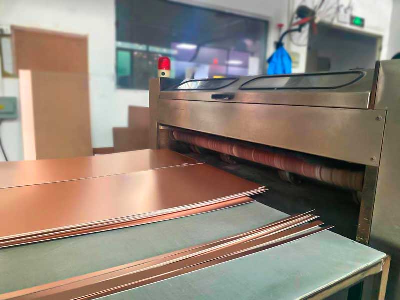
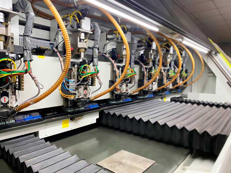
Thin boards behave differently on the production line. Material cutting must be accurate so that panel utilization stays high and edges remain clean. Drilling and routing generate mechanical stress, and a thin core can deform or chip if parameters are pushed. Lamination needs careful control of pressure, temperature and resin flow to avoid voids, delamination and warpage. Every one of these steps interacts with the others, so a change in one place should trigger a review of the rest. Process discipline matters more on lightweight builds, not less.
Panelization is an underrated lever. Efficient nesting reduces substrate waste and keeps unit cost sensible on small lots. The panel design must also support the assembly process, with adequate rails and fiducials for thin material. Handling matters too, because thin boards flex when picked up and can be damaged before test. Our PCB assembly engineers review panel design alongside fabrication to avoid these problems. A short first-article check catches most of them before the lot runs.
Flexible and Rigid-Flex Options
Flexible circuits solve problems that rigid boards cannot. They bend within defined limits, so they fit curved housings and moving joints. In wearable and handheld products, a flex circuit can replace a bundle of wires and connectors, which reduces both volume and weight. Rigid-flex structures go further by combining stiff sections for components with flexible interconnections between them. This removes separate boards and the connectors that would join them. The result is often a simpler assembly with fewer interfaces to fail.
These technologies demand their own design rules. Bend radius, copper grain direction and coverlay openings all affect fatigue life. Engineers should keep bending away from plated holes and sharp copper edges. The mechanical envelope must be agreed with the housing designer early, because a flex path cannot be rerouted late without cost. Suppliers should demonstrate experience with the specific structure before the design is frozen. Buyers can ask for sample builds and inspection records as evidence.
Assembly and Thermal Balance
A light bare board can still become heavy after components are added. Package selection, connector style and component count all contribute to final mass and height. SMT placement generally supports higher density than through-hole assembly, which helps shrink the footprint. Stencil design and reflow profile must suit thin substrates, since they heat faster and can warp. Support tooling may be needed to keep the board flat through the oven. These details belong in the process plan, not in a late fix.
Thermal management is the constraint most often forgotten in lightweight work. Removing material reduces the board’s ability to spread heat away from processors, radios and power circuits. Thermal vias, local copper thickness and careful component spacing help restore the path. Where power density is high, an aluminum-backed or metal-core solution may be the practical answer. The choice depends on enclosure airflow, duty cycle and ambient conditions. Our PCBA testing step verifies function under load before shipment.
Inspection and Test Coverage
Inspection should confirm the parameters that lightweight designs depend on. Board thickness, layer registration, hole quality and copper thickness are all measurable and should be recorded. Warpage deserves attention because thin boards are more sensitive to heat and handling. Electrical test catches opens, shorts and insulation faults that visual checks miss. Functional test then confirms the assembled board behaves as the device requires. Each step adds confidence, and the records show whether the process stayed inside its window.
Test coverage should match the risk of the product. A monitoring device that a clinician relies on deserves more verification than a simple accessory. In-circuit test, functional test and burn-in each answer a different question, so the plan should state what each one covers. Buyers should ask which tests run on every unit and which run on samples. They should also ask how failures are handled and whether the cause is investigated. Our turnkey PCB assembly service keeps fabrication, assembly and test under one schedule.
Supplier Checks Before Release
Supplier selection decides how much of this discipline actually happens. A capable partner reviews files before quoting, raises questions early and documents the answers. It can explain why a stackup was chosen and what tolerance each feature needs. It tracks material certificates and keeps approved alternates ready. It reports process data honestly when something drifts. These habits are visible during an audit, and they predict performance better than a low unit price does.
Buyers should request the first-article report, the inspection plan and the test summary as routine documents. They should confirm how component sourcing is handled, since a substituted part can change mass, height or thermal behavior. Our component procurement process checks specifications against the approved list before parts reach the line. A written change notification agreement closes the loop. With those controls in place, a lightweight design moves from prototype to repeat production without surprises.
The practical takeaway is simple. Set the weight target from the product, choose materials and stackup against real constraints, and confirm every reduction with process data. Ask the supplier for the stackup rationale, the first-article record and the test plan before you release the order. Those three documents tell you more about capability than any brochure, and they protect the schedule once volume begins.